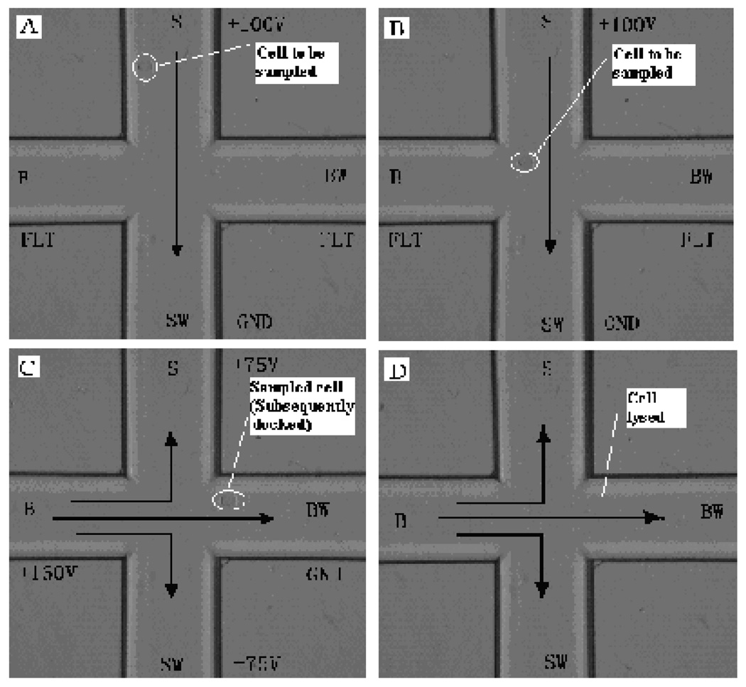
Fig. 2.
Photographs showing a single rat hepatocyte being transported, docked (adhering) and lysed in microfluidic channels. Arrows indicate the direction of liquid flow. (A) & (B): A cell was loaded; (C): the cell was injected from the sample channel into the separation channel, and then docked at an appropriate site on the channel walls; and (D): the docked cell was lysed in the MCE running buffer by means of electrical potentials and ready for MCE-CL separation.

