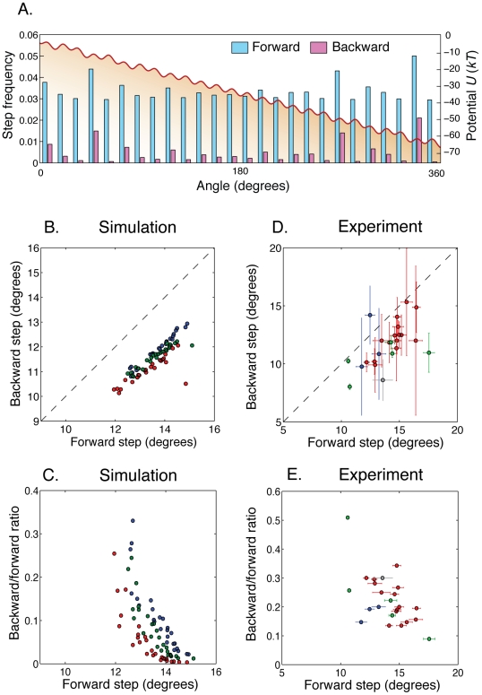
Figure 4. Absolute position of the rotor matters.
A. A typical approximately 26-fold periodic tilted potential  (red line) used in our simulations. For each of the 26 barriers in
  , we show the frequencies of forward and backward steps across that barrier obtained analytically from first-passage theory (see Materials and Methods). Backward steps occur much more frequently at low barriers. B. Average backward and forward step sizes for each of the 26 barriers around the circle. Each color corresponds to a simulation with a different choice of the potential
  . C. The ratio of backward over forward step counts for a given barrier decreases with the average forward step size (colors as in B). D and E. Same as B and C, but with experimental data [1]. Each color corresponds to a different cell. For each cell and each position around the circle, we show a data point only if there were at least 10 backward steps.

