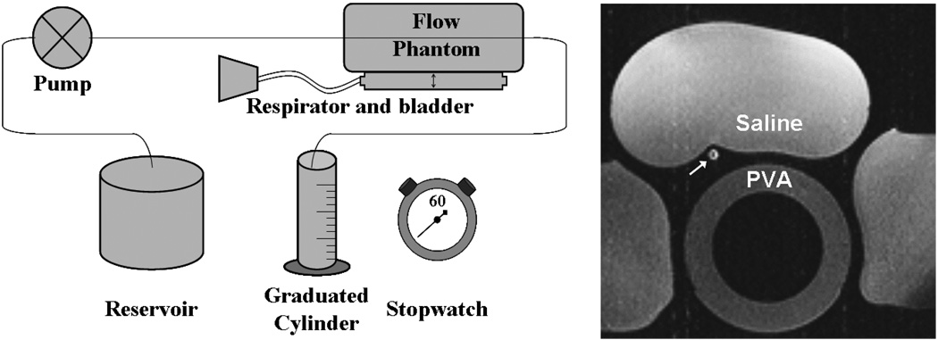
Figure 2.
Schematic of phantom flow setup consisting of a programmable flow pump, vessel phantom resting atop respiratory bladder, and graduated cylinder for timed collection of flow. A axial image of the in vitro setup shows the phantom vessel in cross-section (white arrow) as well as saline bags and PVA phantom.

