
Figure 1. Schematic diagram illustrating the locations of the fluorescent donor (D), AlexaFluor 488 (AF488), and nonfluorescent quencher (Q), QSY9.
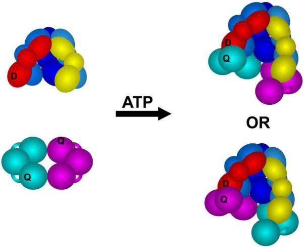
The five-subunit core, γ (shades of blue), δ (yellow), and δ’ (red), of the γ complex (γ3δδ’χψ) is shown in this diagram. Each subunit is composed of three globular domains represented by spheres and ovals. The χ and ψ subunits are omitted from the figure, but present in the complex used in all experiments. The δ’ subunit (red) of the γ complex was covalently labeled with AF488 (D) and the β clamp was covalently labeled with QSY9 (Q). The β-clamp is a dimer of identical subunits each containing three globular domains, and there are two quencher sites within each clamp, one quencher on the cyan subunit and a second on the magenta subunit. Given the C2-axis of symmetry through the center of the ring-shaped clamp, the donor on the δ’ subunit should be near a quencher when the γ complex binds β in either orientation.