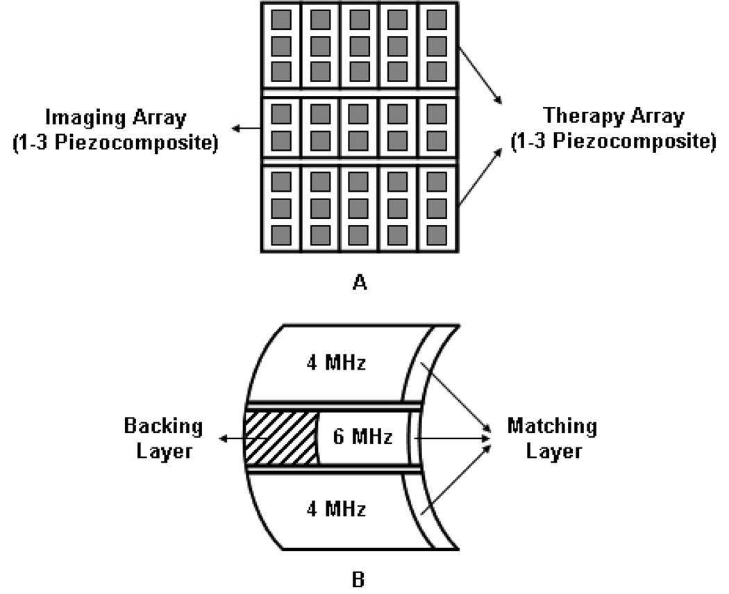
Fig 1.
Simplified schematic diagram of IMCPA transducer with 5 × 3 elements. (a) The front view of IMCPA without a matching layer. (b) The side view of IMCPA with a matching layer. All arrays had 1–3 piezocomposite structures and their surfaces had a common focal point in elevational direction. The center imaging array had a backing layer to increase the bandwidth and the outer therapy arrays had air backings to maximize transmission of ultrasound. A matching layer would also increase the transmission efficiency of IMCPA.

