
Fig 3. Creation of synthetic cephalograms.
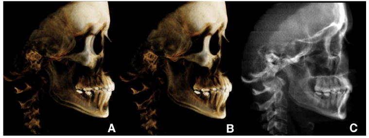
A, unoriented volume; B, oriented to obtain the correct head rotation (note the difference between the orbits and zygomatic bone); C, once oriented, the cephalogram was generated or has been generated (InVivoDental).