Abstract
Large-tip-angle multidimensional RF pulse design is a difficult problem, due to the nonlinear response of magnetization to applied RF at large tip-angles. In parallel excitation, multidimensional RF pulse design is further complicated by the possibility for transmit field patterns to change between subjects, requiring pulses to be designed rapidly while a subject lies in the scanner. To accelerate pulse design, we introduce a fast version of the optimal control method for large-tip-angle parallel excitation. The new method is based on a novel approach to analytically linearizing the Bloch equation about a large-tip-angle RF pulse, which results in an approximate linear model for the perturbations created by adding a small-tip-angle pulse to a large-tip-angle pulse. The linear model can be evaluated rapidly using non-uniform fast Fourier transforms, and we apply it iteratively to produce a sequence of pulse updates that improve excitation accuracy. We achieve drastic reductions in design time and memory requirements compared to conventional optimal control, while producing pulses of similar accuracy. The new method can also compensate for non-idealities such as main field inhomogeneties.
Keywords: MRI, RF pulse design, large-tip-angle RF pulse design, multidimensional excitation, parallel excitation
I. Introduction
Small-tip-angle multidimensional RF pulses have been proposed for several applications in MRI, including reduced FOV imaging [1], [2], simultaneous spatial and spectral selective excitation [3]-[5], transmit field inhomogeneity compensation [6], and the reduction of susceptibility artifact in fMRI [7], [8], among others. In the small-tip-angle regime, the Bloch equation that governs excitation can be approximated by a linear, Fourier model that is accurate when the pulse being designed excites small tip-angles [9]. As a result, pulses can be designed rapidly using e.g., linear filter design principles [10], [11], gridding and FFTs [12], or non-uniform FFTs (NUFFTs) and iterative algorithms [13].
Large-tip-angle multidimensional pulses have been proposed for comparatively fewer applications, among them multidimensional and spectral-spatial refocusing [14], [15], transmit field inhomogeneity compensation at large tip-angles [16], and three-dimensional volume-selective tagging [17]. A potential explanation for the relative brevity of this list is the difficulty of designing such pulses. Under special conditions, the small-tip-angle Fourier model extends to large tip-angles [18], though in general it becomes inaccurate beyond 45 degrees, and the nonlinearity of the Bloch equation must be considered. In the aforementioned applications, pulses were designed either by a global search routine such as simulated annealing, or by segmenting the pulses into many successive small-tip-angle pulses that were designed via Fourier analysis, and were then weighted by a one-dimensional envelope designed with a one-dimensional large-tip-angle pulse design method (such as Shinnar-Le-Roux (SLR) [11]). For example, a two-dimensional echo-planar (EP) 180-degree pulse can be designed using the latter approach by applying sinc pulses along the frequency-encoded dimension of the trajectory, and weighting these pulses by an SLR-designed envelope in the phase-encoded dimension. While this may produce satisfactory pulses for many applications, it is non-ideal because it places constraints on the desired excitation patterns, which must be multiplicatively separable, and it precludes the incorporation of scanner non-idealities such as transmit field inhomogeneity and off-resonance. Global search routines do not impose these limitations, but the memory and computation time they require makes them impractical for patient-tailored pulse designs, and discourages their use in general. For these reasons, a fast, general multidimensional large-tip-angle pulse design method is desirable. The development of such a method may inspire new applications for these pulses.
Recently, there has been renewed interest in multidimensional large-tip-angle pulse design, driven by the emergence of parallel excitation [19], [20]. In parallel excitation, localized coils driven by independent RF waveforms are employed as a mechanism for spatially encoding RF energy deposition. Because localized coil (or sensitivity) encoding is imposed instantaneously, one can create shorter pulses by trading gradient encoding for sensitivity encoding. Parallel excitation presents new challenges to the pulse designer, since coil sensitivity maps can change between patients, requiring pulses to be designed rapidly online. Though several methods have been proposed for large-tip parallel pulse design [21]-[24], all either require many Bloch equation simulations (making online design difficult), achieve reduced compute time via pulse segmentation as described above, or require additional pulse length to correct large-tip angle distortions in small-tip-designed pulses.
Among the existing large-tip parallel pulse design methods is an extension to parallel excitation [21] of the optimal control pulse design method [25], originally introduced for one-dimensional slice-selective pulse design. Based on optimal control theory [26], the method is an iterative algorithm that designs an RF pulse to minimize a least-squares cost function. At each iteration, the Bloch equation is evaluated using the current pulses. Gradients with respect to the Bloch equation and the cost function are also computed, and the pulses are updated by stepping in the negative gradient direction. The cost function framework used in optimal control allows the user to easily include regularizers, or to jointly refine gradient waveforms. Though the method is desirable in terms of generality and pulse quality, evaluation of the Bloch equation at each iteration is computationally expensive, limiting its practical use.
In this paper, we introduce a fast version of the optimal control pulse design method for multidimensional and parallel excitation. We accelerate the technique by replacing the Bloch equation with a linear model that can be evaluated rapidly, for example using non-uniform fast Fourier transforms (NUFFTs) [27]. Previously, we investigated a method [28] that uses the small-tip-angle equation for this purpose, a choice that was driven by intuition from the small-tip-angle regime. The approach we take here is to analytically linearize the Bloch equation around an underlying pulse, resulting in a model that accurately relates small perturbations in an RF pulse to small perturbations in magnetization. We compare the new algorithm to conventional optimal control, in terms of excitation accuracy, compute time, and memory requirements.
II. Theory
A. The Cayley-Klein parameters
For the sake of simplicity and generality, in this article we work with the Bloch equation in the spin-domain [11], [29]. In the spin domain, the rotation of a body by an angle ϕ about a vector n = (nx, ny, nz) can be described by the complex-valued Cayley-Klein parameters (α, β):
| (1) |
| (2) |
The Cayley-Klein parameters can be related to the Euler angles that describe the orientation of a body in three-dimensional space. This compact notation allows a rotation in three-dimensional space to be conveniently represented as a 2 × 2 unitary matrix. For a given RF pulse b (t) and gradient waveform G (t), the α (x) and β (x) representing the rotation they induce at a spatial location x is obtained by solving the spin-domain Bloch equation:
| (3) |
where ‘*’ denotes complex conjugate. The magnetization following excitation can then be obtained as:
| (4) |
where and are the transverse and longitudinal magnetization components before and after excitation, respectively, and Mxy = Mx + iMy.
B. The small-perturbation approximation
Two linearizations of the Bloch equation currently exist that are useful for multidimensional RF pulse design. The first is the small-tip-angle approximation [9], which is a linearization of the Bloch equation about a zero pulse, with zero initial tip-angle. It has found a wide variety of uses in small-tip-angle multidimensional pulse design. The small-excitation approximation [18] generalizes the small-tip-angle approximation to nonzero initial tip-angles, and has been used to analyze the performance of multidimensional large-tip-angle RF pulses. In this section we introduce a third linearization of the Bloch equation about a nonzero pulse, with nonzero initial tip angle. We call this linearization the small-perturbation approximation. In later sections we will show how it can be used to rapidly design large-tip-angle multidimensional RF pulses.
Consider a parallel excitation scenario in which we are given a set of (possibly) large-tip-angle RF pulses {b1, . . . , bR} for R coils. We call these pulses the baseline pulse set. At a spatial position x, the spin-domain Bloch equation for these pulses is:
| (5) |
where and sr (x) is coil r’s transmit sensitivity (B1+) pattern. We have dropped the time dependence of btot, α, β and the gradient field G, and the spatial dependence of btot, α, and β for brevity. Our first goal is to derive a differential equation for the perturbations to (α, β) that are induced by a pulse set that is added to {b1, . . . , bR}. To obtain this equation, we subtract (5) from the Bloch equation for the summed pulse set , yielding:
| (6) |
Multiplying this out gives the following coupled pair of differential equations:
| (7) |
| (8) |
This pair of equations seems unsolvable analytically, so we simplify it using approximations inspired by the small-excitation approximation [18]. We expect that and will be small compared to other terms in (7) and (8), so we approximate them as zero. Additionally, because we want to decouple the equations for and , we approximate and as zero (we elaborate on this choice in Section VI). These approximations leave:
| (9) |
| (10) |
Using initial conditions and , the solutions to these equations, evaluated at the end of the pulses, are:
| (11) |
| (12) |
where T is the pulse length and .
It is interesting to note that the small-excitation approximation [18] is a special case of Eqs. 11 and 12. In that scenario, btot (x, t) = 0, so the baseline Cayley-Klein parameters are:
| (13) |
| (14) |
Plugging these into (12) and (11), rearranging the k-space integral limits in (11), and summing the results with (α, β) yields
| (15) |
| (16) |
which correspond to the parallel excitation version of the small-excitation approximation. The small-tip-angle approximation then follows as a special case of the small-excitation approximation in which magnetization is initially at equilibrium [18].
To implement (11) and (12) on a computer, we discretize them to Nt time points and Ns spatial points, yielding:
| (17) |
| (18) |
i = 1, . . . , Ns, where , , , , and Δt is the sampling period. Expressed in matrix-vector form:
| (19) |
| (20) |
| (21) |
| (22) |
where . We use the linear relationships of (15) and (17) to compute approximate perturbations to the Cayley-Klein parameters, and , given pulse perturbations .
C. The RF pulse design problem
Given an initial magnetization state, we can use the perturbed Cayley-Klein parameters to compute magnetization perturbations [29]. For example, if magnetization is initially at equilibrium with magnitude M0, the magnetization perturbations are given by:
| (23) |
| (24) |
In these approximations we have dropped terms that are quadratic in , allowing us to use a “linear” Conjugate Gradient algorithm [30] in our method. We then form a cost function to design :
| (25) |
where contains the sampled desired transverse and longitudinal magnetization patterns, contains the patterns excited by the baseline pulses {b1, . . . , bR}, as computed via Bloch simulation, and contains the magnetization perturbations computed using 23 and 24. The 2Ns×2Ns diagonal matrix W contains spatial weights that can be used to specify a region of interest (ROI), or differentially weight the transverse and longitudinal magnetization components. The Tikhonov regularization parameter λ balances excitation error with total pulse power.
Though we have posed the above pulse design problem (25) in terms of perturbed magnetization, there are alternatives to this formulation that would also make use of our fast model. First, one could retain all terms in Eqs. 23 and 24 and use a “nonlinear” Conjugate Gradient algorithm [31]. This may yield improved convergence properties compared to the approximated model, however, it would come at the cost of increased computational complexity due to quadratic cross-terms. One could also use a magnitude least-squares formulation, in which the pulse is designed to excite a target |mxy|, but is allowed to excite any phase pattern [32]. Alternatively, one could design pulses directly in the spin domain. This option may be particularly attractive when designing spin-echo pulses, since the magnetization produced by a crushed spin echo pulse is mxy = iβ2M0 (for magnetization initially along the +y axis) [11]. It is therefore natural to design spin echo pulses according to a desired β2 profile. However, in general, desired pattern specification in the spin domain is less intuitive to the pulse designer.
D. Fast computation of perturbed Cayley-Klein parameters
Though the matrices B and A in Eqs. 19 and 21 contain Fourier kernels, overall they are non-Fourier due to and βij, respectively. This prevents us from directly using NUFFTs to evaluate matrix-vector products involving B and A. Focusing on for the moment, to enable fast computation we seek separable approximations of the form [33]:
| (26) |
where L is small. Substituting this approximation into (20) yields, in matrix form,
| (27) |
where in this context G is an Ns × Nt NUFFT operator with elements . We evaluate (27) efficiently using L NUFFT calls. Let and . The length-Nt rows dl of D can be interpreted as temporal basis vectors over which the rows of the matrix are expanded, with spatially-varying coefficients contained in the length-Ns columns cl of C. One approach to choosing C and D would be to compute the SVD of α*. This choice would yield C and D that minimize the Frobenius norm
| (28) |
Two issues are encountered in directly computing the full SVD of α*; the first is illustrated in Fig. 1a. This figure plots the singular values, in descending order, of an α* matrix obtained by simulation of an accelerated spiral pulse, as well as from an accelerated echo-planar (EP) pulse. In both cases α* has a large number of singular values, so low-rank (i.e., small L) approximations to it will be highly inaccurate. However, it is possible to substitute an alternative form of into Eq. 11 that results in a non-Fourier matrix (denoted as α̂*) with only a few significant singular values. We derive this new form from the small-excitation regime, in which the baseline pulses {b1, . . . , bR} are zero. In that case, is given by (see [18], Eq. 14):
| (29) |
Substituting this analytical form into (20) yields:
| (30) |
Because this equation contains no non-Fourier terms, an NUFFT can be used to directly evaluate it. In essence, to arrive at this expression we have divided by its’ Fourier small-excitation solution, and absorbed that solution into the existing Fourier kernel, resulting in a unity term that need not be expanded, i.e., has one non-zero singular value. We have found empirically that even for large-tip-angle pulses, the matrix α̂* with elements
| (31) |
has only a few significant singular values. Figure 1a illustrates this property for the spiral and EP pulses. Therefore, an accurate low-rank approximation to α̂* can be determined via SVD, enabling fast computation of Eq. 19. Figure 1b shows that the same result is true for βij; i.e., that the gradient-frame matrix β̂ with elements
| (32) |
has only a few significant singular values compared to β. Intuitively, in the α* case, we use our separable approximation to represent the deviation from the Fourier small-excitation model for α* that is caused by the large-tip-angle pulses. It is interesting to note that β̂ij and correspond to the spin domain parameters observed in a frame rotating at the spatially- and temporally-varying frequency induced by the gradient fields, that we refer to as the gradient frame. We can transform α* and β to and from the gradient frame via division and multiplication with .
Fig. 1.
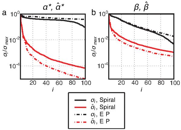
(a) The first 100 normalized singular values σi and σ̂i, plotted in descending order, of α* and α̂*, respectively. (b) The same, for β and β̂ The matrices were obtained by Bloch simulation of small-tip-designed accelerated spiral and EP pulses, that were scaled to excite large-tip-angles. The gradient frame parameters α̂* and β̂ possess few significant singular values compared to the standard rotating frame parameters α* and β, permitting accurate low-rank approximations to these matrices.
The second computational issue is that too much memory and time would be required to compute the SVD of the full α̂* matrix in practice. To avoid this cost, we compute the SVD of a reduced α̂* matrix that is obtained by Bloch simulation of {b1, . . . , bR} over a subset of spatial locations, so that the reduced matrix has size , where . The simulated locations are chosen to be uniformly distributed over the range of flip angles in the desired pattern. To choose the locations, we divide the range of flip angles into Nb bins, , then pull locations from each bin by arranging the location indices within that bin lexicographically and taking evenly-spaced indices. An SVD of the reduced matrix yields the L × Nt temporal basis vector matrix D that we use to approximate α̂* (x, t) at all spatial locations, per (26). Once the matrix D is determined, the least-squares optimal coefficient matrix C is determined as:
| (33) |
where the second equality follows from the orthogonality of singular vectors, and ’ denotes Hermitian transpose. We compute the product D (α̂*)’ as a running sum during Bloch simulation of {b1, . . . , bR} for all spatial locations, obviating the need to store the full matrix α̂*.
We apply the same techniques to approximate β̂, which we expand as
| (34) |
This is substituted into Eq. 22, yielding
| (35) |
The matrix is computed using the SVD of a reduced β̂ resulting from Bloch simulation of the baseline pulses over a subset of spatial locations. It is then used to compute the least-squares optimal via:
| (36) |
which is calculated as a running sum during Bloch simulation for all spatial locations.
E. The Fast Optimal Control Algorithm
The algorithm alternates between Bloch simulations to update the α̂* and β̂ expansions and CG iterations to design . The required steps are summarized as follows, given an initial set of baseline pulses {b1, . . . , bR}.
Fast Optimal Control Algorithm
Simulate {b1, . . . , bR} using a Bloch equation simulator over a subset of spatial locations, yielding α̂* and β̂ for these points.
Compute the SVDs of the reduced α̂* and β̂ matrices to obtain temporal basis matrices D and F.
Repeat the simulation of {b1, . . . , bR} for all spatial locations. Use (33) and (36) to compute the matrices C and E via running sums, to conserve memory. Also store the last columns of α* and β in preparation for computing the perturbed magnetization.
Using (19) and (21) to compute and and , with the approximations of (27) and (35) for the matrices B and A, and computing perturbed magnetization using (23) and (24), apply the CG algorithm to find the that minimize (25) iteratively.
Set and return to step 1 until a convergence criterion is met.
III. Pulse Design
We used the fast optimal control method to design two-dimensional RF pulses, and compared it to small-tip-angle [34] and conventional optimal control RF pulse design [21] in simulations. Desired flip angle patterns were specified on a 64 × 64 grid, with a FOV of 24 cm × 24 cm, and were blurred by convolution with a Gaussian kernel of FWHM = 1.2 cm to reduce ringing in the resulting excitation patterns. Bloch equation simulations for pulse design were performed on the same grid, while simulations for final error computation and comparison were performed on a finer 128 × 128 grid with the same FOV. Spins outside the ROI were not simulated.
The fast optimal control method used 25 CG iterations at each alternation. The SVD’s for determining the α̂* and β̂ expansions were calculated using the results of a reduced Bloch simulation over a set of 60 representative spatial locations. The expansions used L = 4 (Eqs. 27 and 35), except in simulation IV-B, where L was varied. The NUFFT algorithm [27] used a 6 × 6 neighborhood for interpolation, and an upsampling factor of 2 in both dimensions. If were designed using an exact perturbation model, we would add them directly to {b1, . . . , bR} at each alternation. However, given that we used an approximate model to design that is most accurate for small perturbation pulse magnitudes, in our simulations and experiments we multiplied by a step size before adding them to {b1, . . . , bR} and simulating the total pulse set. The step size was initially set to 1 at each alternation, allowing large perturbation pulse magnitudes, and therefore potentially large reductions in excitation error. If addition of the perturbation pulses resulted in a Normalized Root-Mean-Square Error (NRMSE) exceeding 99.99% that of the previous alternation’s pulse set, then the step size was reduced by a factor of 2 and the pulses were re-added and simulated. We defined NRMSE as the error between the desired pattern and the Bloch-simulated magnetization pattern :
| (37) |
Alternations were stopped when the step size fell below 2-4.
The method of [21] was used for conventional optimal control pulse design. It optimized pulses using gradient descent, with a step size that was chosen to maximize downhill descent per iteration, while avoiding divergence. The method was stopped at 100 iterations.
The spatial-domain small-tip design method of Ref. [34] was used to design initial pulses for both large-tip methods, with 100 CG iterations and the same desired flip angle pattern and NUFFT parameters. Small-tip-angle design was initialized with zero pulses. In all design methods, pulses were designed with small λ, the total pulse Tikhonov regularization parameter in Eq. 25, except in Simulation II, where λ was varied for the fast optimal control method. Bloch simulations for pulse design were initialized with all magnetization in Mz. All pulse designs and simulations were performed in MATLAB R2007a (Mathworks, Natick, MA, USA), on a 3.4GHz Pentium IV workstation with 2GB RAM.
IV. Simulations
Simulations of parallel excitation were carried out assuming an 8 element active rung transmit array [35]. Transmit sensitivity patterns were obtained via Finite-Difference Time-Domain simulation [36] of the array at 3.0 Tesla, using a phantom modeled as a 22 cm diameter lossy cylinder with σ = 0.3 S/m and εr = 80 (Fig. 2). The ROI for pulse design and error calculation was the phantom interior. The desired flip angle pattern, shown in Fig. 3, was a rectangular block that was centered in the phantom, with dimensions 10 cm × 5 cm.
Fig. 2.
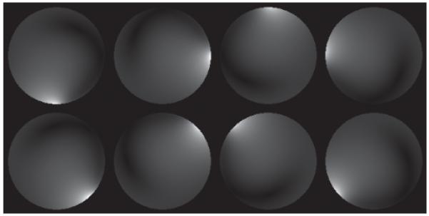
Magnitude of B1+ patterns used in simulations of eight-channel parallel excitation.
Fig. 3.
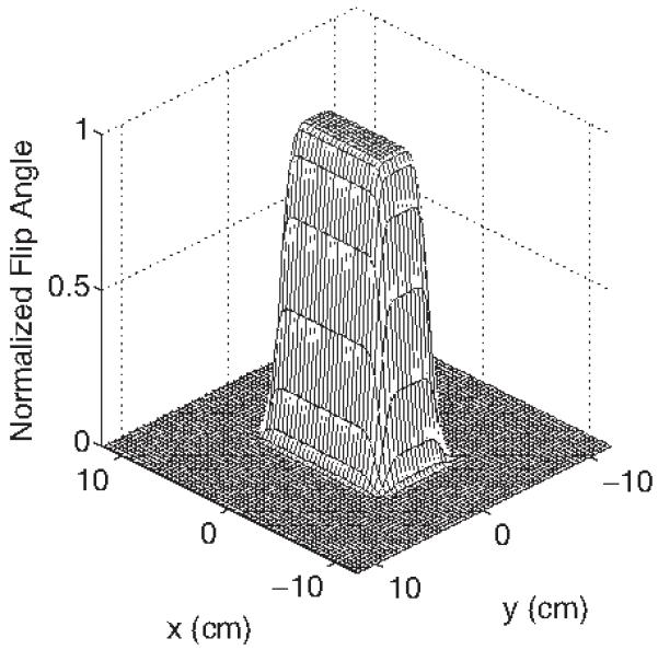
Desired flip angle pattern used in simulations, which was a smoothed 10 cm × 5 cm rectangular block, whose peak was scaled to π and for pulse design.
We designed pulses using spiral and echo-planar (EP) excitation k-space trajectories. Spiral trajectories were single-shot spiral-out with the parameters: maximum amplitude = 4 G/cm, maximum slew rate = 18 G/cm/ms. Acceleration was achieved via undersampling in the radial direction, resulting in reduction of the excitation field of view (XFOV) of the individual coils’ excitation patterns. We define Speedup Factor (SF) as the ratio of the fully-sampled XFOV to the accelerated XFOV of a given trajectory. EP trajectories were designed using the parameters: maximum amplitude = 4 G/cm, maximum slew rate = 15 G/cm/ms. For these trajectories, acceleration was achieved via undersampling in the blipped (phase-encoded) dimension. The spatial resolution for all trajectories was 0.75 cm, which is twice that of the grid on which the desired patterns were specified. The sampling period for all pulses was 4 μs.
A. Speedup Factor
In the first simulation, we compared the performance of the three design methods across a range of speedup factors. We designed - and π-excitation pulses with speedup factors from 2.4 to 6, corresponding to an XFOV range from 10 cm down to 4 cm.
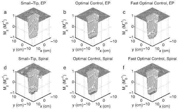
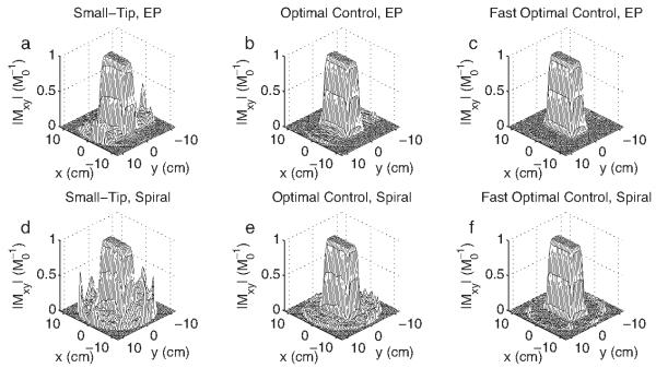
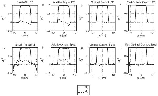
Figure 4 plots error versus speedup factor for the three pulse design methods, and shows that the optimal control methods always improved excitation error relative to small-tip-designed pulses. The improvements were larger for EP pulses than for spiral pulses. For all spiral pulses and for -EP pulses, the fast optimal control method nearly always achieved equal or better accuracy than could be reached with 100 iterations of conventional optimal control. For EP π-pulses, fast optimal control reached similar but higher error than conventional optimal control. The inversion patterns shown in Fig. 5 demonstrate that the optimal control methods improved the accuracy of π-pulses by reducing erroneous excitation outside the desired inversion region, and by improving uniformity inside the inversion region. In the EP case, both optimal control methods (Fig. 5b) corrected the slow-dimension bandwidth-narrowing effect [15] that plagues the small-tip-designed pulse (Fig. 5a), however, pulses designed with the fast method produced patterns with less uniform Mz than the conventional method. Figure 6, which shows the magnitude of excitation patterns produced by -pulses, and Fig. 7, which shows Mx and My profiles through the centers of these patterns, demonstrate that the optimal control methods improved the accuracy of -pulses by both reducing erroneous excitation outside the desired excitation region, and by improving phase accuracy. Our desired pattern specifies that all excited magnetization should lie along the Mx direction, corresponding to zero phase, which the optimal control-designed pulses achieved. Figure 7 also demonstrates an advantage of the fast optimal control method over the additive angle method for fast parallel large-tip pulse design method previously introduced by our group [28]. While both the additive angle method and the fast optimal control method can produce pulses that are accurate in terms of desired magnetization magnitude, the fast optimal control method provides the ability to control excitation phase, while the goal of the additive angle method is to improve excitation magnitude accuracy only.
Fig. 4.
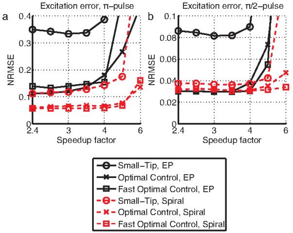
Error vs. speedup factor for the small-tip-angle method, the conventional optimal control method, and the fast optimal control method, for π- and -sprial and EP pulses. The optimal control methods produce pulses that are consistently more accurate than those produced by the small-tip-angle methods. The fast optimal control method achieves similar error to the conventional optimal control method.
Fig. 5.
Simulated Mz patterns produced by π-pulses designed with the small-tip-angle (a,d), optimal control (b,e), and fast optimal control (c,f) methods, for an EP trajectory (a-c) with speedup factor = 3 (XFOV = 8 cm, pulse length 3.34 ms), and a spiral trajectory (d-f) with speedup factor = 4.8 (XFOV = 5 cm, pulse length 1.16 ms). The M z patterns excited by the optimal control methods are of higher quality than those excited by small-tip-designed pulses. The optimal control methods excite patterns of similar accuracy, though in the EP case pulses designed with the fast method excite a less uniform inversion region than the conventional method.
Fig. 6.
Simulated Mxy patterns produced by -pulses designed with the small-tip-angle (a,d), optimal control (b,d), and fast optimal control (b,d) methods. Pulses designed using the optimal control methods produce patterns with reduced erroneous excitation outside the block, for both the EP trajectory (a-c) (speedup factor = 4, XFOV = 6 cm, pulse length 2.7 ms) and the spiral trajectory (d-f) (speedup factor = 6, XFOV = 4 cm, pulse length 1 ms). The fast optimal control method produced pulses of higher accuracy than could be achieved in 100 iterations of the conventional method.
Fig. 7.
Profiles through the center (y = 0) of the excited magnetization patterns of Fig. 6, as well as for additive angle-designed pulses [28]. For both EP and spiral pulses, the optimal control-designed pulses excite patterns with more uniform phase, as evidenced by the smaller imaginary (My) magnetization components in (c,d,g,h).
Design times for the two optimal control methods are compared in Fig. 8. The figure plots the design times for EP and spiral π-pulses. For the EP pulse, the fast method converged to a design NRMSE, measured on the 64 × 64 design grid, of 11.1% in 3.9 minutes. To reach this same level of error, the conventional method required 52 iterations, which took 85 minutes. In this case, the fast method achieved a 21.8-fold reduction in design time. For the spiral π-pulse, the fast method converged to a design NRMSE of 0.87%. In contrast, the design error reached by the conventional method after 100 iterations was NRMSE = 2.81%, in 67.5 minutes. The fast optimal control method reached this same error in 2.3 minutes, corresponding to a 29.4-fold reduction in design time. When run for 10000 iterations (2.2 days), the conventional method reached a design NRMSE of 1.63%, which the fast method reached with a 527-fold reduction in compute time.
Fig. 8.
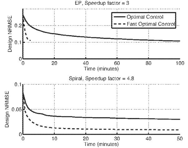
Comparison of design times for conventional and fast optimal control methods. For the EP case (π-pulse speedup factor = 3), a 21.8-fold reduction in design time was achieved by the fast method. For the spiral case (π-pulse, speedup factor = 4.8), the conventional method did not converge in 100 iterations, though the fast method achieved the conventional method’s 100-iteration-error with a 29.4-fold reduction in design time.
B. Parameter selection and tradeoffs
In this simulation we investigated the influence of fast optimal control design parameters. We repeated fast optimal control designs of π-pulses, and varied parameters that may influence final excitation error, peak total pulse power, and the rate of convergence.
We first varied the total pulse Tikhonov regularization parameter λ (Eq. 25) from log10 λ = -1 to log10 λ = 2.25 for EP pulses with a speedup factor of 3 and for spiral pulses with a speedup factor of 4.8. This parameter adjusts the balance between excitation error and integrated pulse power. As λ is increased, the algorithm trades excitation error for lower pulse power, and therefore lower peak RF magnitude, as shown in Figs 9(a,b). This shows that, as in conventional optimal control pulse design [21], the user can adjust λ to balance this tradeoff in a given design scenario.
Fig. 9.
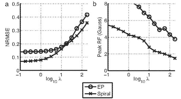
The total pulse Tikhonov regularization parameter (λ) can be tuned to balance excitation accuracy (a) against peak RF magnitude (b).
We then performed designs over a range of L values, from 1 to 10, where L is the expansion order of our approximations to the matrices α* and β in Eqs. 27 and 35, for EP pulses with speedup factors of 3 and 4, and for spiral pulses with speedup factors of 4.8 and 6. Figure 10a plots the final NRMSE against L. Interestingly, for the lower speedup factors the final error was approximately independent of L, especially for spiral pulses. Figure 10b plots the design NRMSE as a function of Bloch/CG alternation, for L = 1 and 10 at the lower speedup factors. This figure indicates, especially for spiral pulses, that while L may not significantly influence the final design error, using a smaller L did cause a greater number of Bloch/CG alternations to be required to reach a low error level. Because L influences the time required to perform each CG design, this result indicates that at lower speedup factors, L should be chosen to optimize design time. For example, if Bloch equation simulations are computationally inexpensive compared to CG iterations, a smaller L may minimize the design time, while if Bloch simulations are very computationally expensive, the required number of simulations can be reduced by choosing larger L.
Fig. 10.
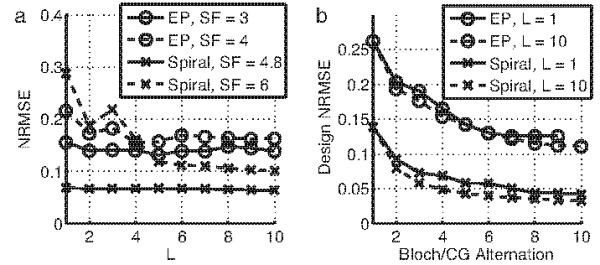
Error versus L. (a) For low speedup factors, excitation accuracy is largely independent of the (α*, β) expansion order, L, but (b) shows that fewer Bloch/CG alternations are required for larger values of L. For higher speedup factors, larger L leads to lower error.
V. Experiments
We performed scanner experiments of parallel excitation along an EP trajectory to compare the performance of fast optimal control-designed pulses with that of small-tip-designed pulses. Experiments were performed on a GE 1.5T Signa Excite Scanner (GE Healthcare, Milwaukee, WI, USA). Pulses were designed for a four-channel parallel transmit system to excite an 3 × 3 cm rectangular region in a 10 cm disc phantom filled with 1% copper sulphate solution. Excitation patterns were then imaged using a GRE sequence.
Transmission was performed using a four-channel loop coil transmit array driven by 300W in-house built power amplifiers that were in turn fed vector-modulated RF signals [37]. An eight-channel cardiac array was used for signal reception. Prior to pulse design, the B1+ fields were mapped using a multi-tip hard-pulse magnetization-prepared B1+ measurement sequence [38]. Figure 11a shows the measured B0 field map in the phantom, and 11b shows the magnitude profiles of the B1+ maps. The coils are strongly coupled, as can be seen from the diffuse shapes of the field magnitude patterns. There is also a small region near the top of the phantom in which B1+ estimation failed, yielding the dark spot in the same place on each coil’s map. The misestimation was likely due to low SNR in this region.
Fig. 11.

(a) B0 field map in the phantom. The maximum resonance offset magnitude was 118 Hz. (b) The |B1+| patterns for each coil.
The EP trajectory was designed with XFOV = 4.5 cm, spatial resolution = 0.5 cm, maximum slew rate = 14.5 G/cm/ms, and sampling period = 4 μs. To achieve realizable RF magnitude near the center of k-space, the central 3 phase encodes were designed with a maximum gradient amplitude of 0.28 G/cm, à la the VERSE technique [39]. The outer phase encodes were designed with a maximum amplitude of 0.73 G/cm. These parameters yielded a pulse length of 9.74 ms. Prior to pulse design, the trajectory was measured on the scanner [40], [41]. Fast optimal control pulses were designed with off-resonance compensation using the modified perturbed spinor model described in the Appendix, with the B0 field map of Fig. 11a as input. The complex exponential representing off-resonant phase accrual was approximated using histogram-based least-squares time segmentation [8], with 8 histogram bins and 4 temporal segments at uniform intervals.
Parameters for the GRE sequence used to image the excitation patterns were as follows: FOV = 20 cm; matrix size = 128 × 128; TR = 300 ms; TE = 12 ms; 2 averages. Excitation gradient waveforms were shifted forward by 140 μs to compensate for delay between RF and gradient channels. Figure 12 shows simulated and imaged excitation patterns. As indicated in the figure, the small-tip-designed pulses produce a spike next to the square that is suppressed by the fast optimal control method. Furthermore, the lower left hand corner of the square is distorted in the small-tip pulses’ pattern, but corrected by the fast optimal control method. The experimental images also contain other erroneous excitation in the top part of the phantom that is not present in the simulated patterns, indicating that it arose from, e.g., errors in the B1+ or B0 field maps, and was not caused by the pulse design.
Fig. 12.
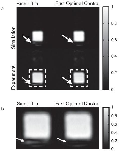
a) Simulation and experimental results. In both the simulation and experiment, a spike is present in the pattern excited by the small-tip-designed pulses that is suppressed by the fast optimal control method (indicated by arrows). The fast optimal control method also corrected a distortion in the lower left hand corner of the excited square. (b) Zoomed regions indicated by the dashed white boxes in (a).
VI. Conclusion and Discussion
We have introduced a new method for fast, general large-tip-angle multidimensional and parallel excitation pulse design. It is a fast version of the optimal control pulse design method, first introduced by Conolly et al [25], and extended to parallel excitation by Xu et al [21]. The new method is derived directly from the spin-domain Bloch equation, by analyzing the difference between the Bloch equation of a set of large-tip-angle pulses plus small perturbation pulses, and the Bloch equation of the small perturbation pulses alone. By approximating a few terms in the difference equations as zero, we were able to derive a Fourier-like relationship between the perturbation pulses and the perturbations they produce in the Cayley-Klein parameters of the large-tip-angle pulses.
There are two central ideas we have introduced that make our method ‘fast’. The first is the linearization of the spin-domain Bloch equation that results in a Fourier-like linear relationship between perturbation pulses and the perturbations they produce, i.e., a linear gradient approximation. This relationship alone could be valuable to a pulse designer, particularly in scenarios where the pulses being designed are parameterized. For example, this may arise when designing the weights on the rungs of a fast-kz trajectory [42], where each rung contains a sinc pulse whose magnitude we wish to optimize to achieve a flat in-plane excitation pattern. In this scenario, Eqs. 19 and 21 could be evaluated exactly for each spoke of the trajectory, avoiding the need for further accelerations. The second innovation we introduced was the translation of the α* and β matrices to the gradient frame of reference. This dramatically reduced the rank of these matrices, allowing us to use low-rank separable approximations to represent them accurately. This idea is necessary if the method is to be feasible when applied to general pulse design scenarios.
Compared to the additive angle method published previously by our group [28], we showed that the new method allows the designer to control excitation phase, which can be important in designing excitation and refocusing pulses. The new method also accommodates off-resonance, which can be important for pulses of longer duration. In terms of computational cost, neglecting SVD computation the additive angle method is equivalent to fast optimal control when only one perturbed parameter is computed, and L = 1. In other words, the additive angle method is faster per iteration than the fast optimal control method, however, that speed comes at the price of increased excitation inaccuracy for longer pulses, and the inability to control excitation phase.
More significantly, we demonstrated that despite the approximations made in deriving the fast optimal control method, it produces pulses of similar accuracy to conventional optimal control. Because we approximate gradients with respect to the Bloch equation and not the entire Bloch equation, it is difficult to predict the effects of our approximations on the final excitation profile. One may reasonably expect that in some cases the new method would converge to profiles with a higher error than conventional optimal control, due to erroneous gradient directions. However, we found that the new fast method consistently produced pulses of similar accuracy to those produced by the conventional method. This suggests that the approximations do not have a significant influence on the accuracy of the final solution in practice. Furthermore, the fast method generally achieved more than an order of magnitude reduction in compute time compared to conventional optimal control, while requiring significantly less memory. Efficient implementation of conventional optimal control requires the storage of 6 Ns × Nt matrices, where Ns is the number of points in the spatial design grid, and Nt is the number of time points in the pulses. The matrices contain the three magnetization components resulting from the forward and reverse Bloch simulations that are required at each iteration. This memory requirement can be restrictive for longer two-dimensional pulse designs, and renders three-dimensional pulse design unfeasible on a workstation. In comparison, the fast method only requires storage of 2L length-Ns vectors and 2L length-Nt vectors, where L ≪ Ns and L ≪ Nt, and NUFFT interpolators. Therefore, the fast method can be used to design a much wider range of pulses.
Due to the relative ease of analysis and presentation of two-dimensional pulses compared to three-dimensional pulses, we chose to focus on the design of two-dimensional spiral and EP pulses in our simulations and experiments. We found that improvements in excitation error using our method were most pronounced in the case of EP pulses. Though only a few applications have been proposed for EP pulses that encode in two spatial dimensions (see, e.g., [43]) the fast optimal control method could also be used to design large-tip-angle spectral-spatial pulses, whose trajectories are similar to EP pulses. Furthermore, our method can be applied to the design of three-dimensional echo-volumar (EV) pulses (also referred to as fast-kz, rungs, and spokes pulses), which are being actively investigated for B1+ inhomogeneity compensation ([42], [44], [45]). Since EV pulses are a three-dimensional generalization of EP pulses, the performance issues encountered in their design will be similar.
A topic for future investigation is the application of our method to designing refocusing pulses. Directly designing refocusing pulses is a more constrained problem than designing an inversion pulse, since inversion pulses can excite magnetization about any vector; they need only produce a π rotation. In our initial investigations, we have found that controlling the phase of π-pulses is a more challenging problem than controlling the phase of -pulses. Simply demanding that pulses rotate magnetization from +Mx to -Mx is not sufficient, since the design algorithm can either produce pulses that rotate magnetization about a transverse-plane (x-y) vector, or pulses that rotate magnetization about the z-axis using the gradient field. Pulses that use the gradient field to rotate magnetization will fail when applied as refocusing pulses. As discussed in Section II-C, to avoid this pitfall we can design the pulses in the spin domain, which allows direct specification of the flip angle and rotation vector at each point in space. However, we have found that it is difficult to reach sufficiently-accurate pulses in this case using the fast optimal control method (it has not been demonstrated using conventional optimal control, either). This is most likely due to the more nonlinear nature of the Bloch equation in the π flip-angle regime, which causes our method to converge to a local minimum of insufficient accuracy. Therefore, it may be necessary to seek new initial pulses other than those provided by small-tip-angle designs, that are closer to the desired pulses. Such initial pulses could be obtained by global search algorithms [14], for a representative set of coil sensitivities.
Another topic for future investigation is alternative decoupling approximations to the ones we made in solving for the approximate perturbed Cayley-Klein parameters. While the terms and in (7) and (8) are likely to always be small, the approximations and were largely driven by our desire to decouple the differential equations. However, we do have cause to believe that these terms are usually smaller than the retained terms (7,9) and (8,10). Focusing on Eq. 7, we know that α* = 1 and at the beginning of any pulse. Furthermore, for realizable pulses Gauss everywhere in time and space. The combination of these facts indicates that the chosen approximations may be the overall best ones to make. We can also imagine cases in which our approximations fail. It may be that, e.g. in (7), at some spatial locations the neglected term will be larger than the retained term . This may occur at spatial locations where the baseline pulses produce a rotation near π, so that α* ≈ 0, and where the perturbation pulses are expected to produce a large . A more sophisticated analysis than the one performed here could lead to more accurate approximations, and perhaps to the segmentation of space and time into disjoint approximation spaces.
Acknowledgment
The authors would like to thank Dr. Steven Wright for providing the coil sensitivity maps used in their simulations.
This work was supported by NIH Grants R01 NS 058576, R01 DA 015410, and R01 EB 005307.
Appendix
Main field inhomogeneities can cause blurring and other distortions in excited patterns. Given a B0 field map Δω (x), we can include off-resonance in our perturbation model to design pulses that do not suffer these distortions. In analogy to the development of off-resonance-compensated small-tip-angle pulse designs [13], accounting for the phase accrued due to non-zero Δω (x) leads to modified definitions for the discretized matrix elements bij and aij:
| (38) |
| (39) |
as well as a modified expression for the gradient frame transformation kernel (now a gradient plus off-resonance frame transformation kernel):
| (40) |
Substituting the transformed parameters (α̂*, β̂) into Eqs. 38 and 39 gives:
| (41) |
| (42) |
These expressions are again non-Fourier, due to the inseparable complex exponentials introduced by the B0 field map. Fortunately, this problem has been previously visited in the pulse design literature [8], and fast computation of the matrix/vector products can be achieved using time- or frequency-segmentation approaches. Both approaches lead to a separable approximation for of the form
| (43) |
which, when substituted into Eqs. 41 and 42 yields, in matrix form,
| (44) |
| (45) |
We evaluate (44) and (45) efficiently using L·S NUFFT calls.
References
- [1].Rieseberg S, Frahm J, Finsterbusch J. Two-dimensional spatially-selective RF excitation pulses in echo-planar imaging. Magn Reson Med. 2002;47(6):1186–1193. doi: 10.1002/mrm.10157. [DOI] [PubMed] [Google Scholar]
- [2].Alley MT, Pauly JM, Sommer FG, Pelc NJ. Angiographic imaging with 2D RF pulses. Magn Reson Med. 1997;37(2):260–267. doi: 10.1002/mrm.1910370220. [DOI] [PubMed] [Google Scholar]
- [3].Meyer CH, Pauly JM, Macovski A, Nishimura DG. Simultaneous spatial and spectral selective excitation. Magn Reson Med. 1990 Aug;15(2):287–304. doi: 10.1002/mrm.1910150211. [DOI] [PubMed] [Google Scholar]
- [4].Zur Y. Design of improved spectral-spatial pulses for routine clinical use. Magn Reson Med. 2000 Mar;43(3):410–420. doi: 10.1002/(sici)1522-2594(200003)43:3<410::aid-mrm13>3.0.co;2-3. [DOI] [PubMed] [Google Scholar]
- [5].Block W, Pauly J, Kerr A, Nishimura D. Consistent fat suppression with compensated spectral-spatial pulses. Magn Reson Med. 1997 Aug;38(2):198–206. doi: 10.1002/mrm.1910380207. [DOI] [PubMed] [Google Scholar]
- [6].Saekho S, Boada FE, Noll DC, Stenger VA. Small tip angle three-dimensional tailored radiofrequency slab-select pulse for reduced B1 inhomogeneity at 3T. Magn Reson Med. 2005 Feb;53(2):479–484. doi: 10.1002/mrm.20358. [DOI] [PMC free article] [PubMed] [Google Scholar]
- [7].Stenger VA, Boada FE, Noll DC. Three-dimensional tailored RF pulses for the reduction of susceptibility artifacts in T2*-weighted functional MRI. Magn Reson Med. 2000 Oct;44(4):525–531. doi: 10.1002/1522-2594(200010)44:4<525::aid-mrm5>3.0.co;2-l. [DOI] [PMC free article] [PubMed] [Google Scholar]
- [8].Yip CY, Fessler JA, Noll DC. Advanced three-dimensional tailored RF pulse for signal recovery in T2*-weighted functional magnetic resonance imaging. Magn Reson Med. 2006;56(5):1050–9. doi: 10.1002/mrm.21048. [DOI] [PubMed] [Google Scholar]
- [9].Pauly JM, Nishimura DG, Macovski A. A k-space analysis of small-tip-angle excitation. J Magn Reson. 1989;81:43–56. doi: 10.1016/j.jmr.2011.08.008. [DOI] [PubMed] [Google Scholar]
- [10].Shinnar M, Bolinger L, Leigh JS. The use of finite impulse response filters in pulse design. Magn Reson Med. 1989;12(1):81–87. doi: 10.1002/mrm.1910120110. [DOI] [PubMed] [Google Scholar]
- [11].Pauly JM, Le Roux P, Nishimura D, Macovski A. Parameter relations for the Shinnar-Le Roux selective excitation pulse design algorithm. Medical Imaging, IEEE Transactions on. 1991;10:53–65. doi: 10.1109/42.75611. [DOI] [PubMed] [Google Scholar]
- [12].Börnert P, Aldefeld B. On spatially selective RF excitation and its analogy with spiral MR image acquisition. MAGMA. 1998 Dec;7(3):166–178. doi: 10.1007/BF02591334. [DOI] [PubMed] [Google Scholar]
- [13].Yip CY, Fessler JA, Noll DC. Iterative RF pulse design for multidimensional, small-tip-angle selective excitation. Magn Reson Med. 2005 Oct;54(4):908–917. doi: 10.1002/mrm.20631. [DOI] [PubMed] [Google Scholar]
- [14].Hardy C, Bottomley P, O’Donnell M, Roemer P. Optimization of two-dimensional spatially selective NMR pulses by simulated annealing. J Magn Reson. 1988;77:233–250. [Google Scholar]
- [15].Pauly J, Spielman D, Macovski A. Echo-planar spin-echo and inversion pulses. Magn Reson Med. 1993 Jun;29(6):776–782. doi: 10.1002/mrm.1910290609. [DOI] [PubMed] [Google Scholar]
- [16].Conolly S, Pauly J, Nishimura D, Macovski A. Two-dimensional selective adiabatic pulses. Magn Reson Med. 1992 Apr;24(2):302–313. doi: 10.1002/mrm.1910240211. [DOI] [PubMed] [Google Scholar]
- [17].Pauly JM, Hu BS, Wang SJ, Nishimura DG, Macovski A. A three-dimensional spin-echo or inversion pulse. Magn Reson Med. 1993 Jan;29(1):2–6. doi: 10.1002/mrm.1910290103. [DOI] [PubMed] [Google Scholar]
- [18].Pauly JM, Nishimura DG, Macovski A. A linear class of large-tip-angle selective excitation pulses. J Magn Reson. 1989;82(3):571–587. [Google Scholar]
- [19].Katscher U, Börnert P, Leussler C, van den Brink JS. Transmit SENSE. Magn Reson Med. 2003 Jan;49(1):144–150. doi: 10.1002/mrm.10353. [DOI] [PubMed] [Google Scholar]
- [20].Zhu Y. Parallel excitation with an array of transmit coils. Magn Reson Med. 2004 Apr;51(4):775–784. doi: 10.1002/mrm.20011. [DOI] [PubMed] [Google Scholar]
- [21].Xu D, King KF, Zhu Y, McKinnon GC, Liang Z-P. Designing multichannel, multidimensional, arbitrary flip angle RF pulses using an optimal control approach. Magn Reson Med. 2008;59(3):547–560. doi: 10.1002/mrm.21485. [DOI] [PMC free article] [PubMed] [Google Scholar]
- [22].Setsompop K, Zelinski AC, Alagappan VA, Fontius UJ, Hebrank F, Schmitt F, Wald LL, Adalsteinsson E. High flip angle slice selective parallel RF excitation on an 8-channel system at 3T; Proceedings 15th Scientific Meeting, International Society for Magnetic Resonance in Medicine; Berlin. 2007.p. 677. [Google Scholar]
- [23].Ulloa JL, Callaghan M, Irarrazaval P, Hajnal J, Guarini M. Calculation of B1 pulses for RF shimming at arbitrary flip angle using multiple transmitters; Proceedings 14th Scientific Meeting, International Society for Magnetic Resonance in Medicine; Seattle. 2006.p. 3016. [Google Scholar]
- [24].Haas M, Ullmann P, Hennig J, Zaitsev M. Two-step small transverse magnetization method for the design of 180° spatially selective RF pulses; Proceedings 16th Scientific Meeting, International Society for Magnetic Resonance in Medicine; Toronto. 2008.p. 1319. [Google Scholar]
- [25].Conolly S, Nishimura D, Macovski A. Optimal control solutions to the magnetic resonance selective excitation problem. IEEE Trans Med Imaging. 1986;5:106–115. doi: 10.1109/TMI.1986.4307754. [DOI] [PubMed] [Google Scholar]
- [26].Bryson AE, Ho Y-C. Applied Optimal Control. Halsted Press; New York, NY, USA: 1981. [Google Scholar]
- [27].Fessler JA, Sutton BP. Nonuniform fast Fourier transforms using min-max interpolation. IEEE Trans Sig Proc. 2003;51(2):560–574. [Google Scholar]
- [28].Grissom WA, Yip CY, Wright SM, Fessler JA, Noll DC. Additive angle method for fast large-tip-angle RF pulse design in parallel excitation. Magn Reson in Med. 2008;59(4):779–787. doi: 10.1002/mrm.21510. [DOI] [PubMed] [Google Scholar]
- [29].Jaynes ET. Matrix treatment of nuclear induction. Phys. Rev. 1955 May;98(4):1099–1105. [Google Scholar]
- [30].Sutton BP, Noll DC, Fessler JA. Fast, iterative image reconstruction for MRI in the presence of field inhomogeneities. IEEE Trans Med Imaging. 2003;22:178–188. doi: 10.1109/tmi.2002.808360. [DOI] [PubMed] [Google Scholar]
- [31].Press WH. Numerical recipes in C. 2nd ed. Cambridge University Press; 1993. [Google Scholar]
- [32].Setsompop K, Wald LL, Alagappan V, Gagoski BA, Adalsteinsson E. Magnitude least squares optimization for parallel radio frequency excitation design demonstrated at 7 Tesla with eight channels. Magn Reson Med. 2008;59(4):908–915. doi: 10.1002/mrm.21513. [DOI] [PMC free article] [PubMed] [Google Scholar]
- [33].Fessler JA, Lee S, Olafsson VT, Shi HR, Noll DC. Toeplitz-based iterative image reconstruction for MRI with correction for magnetic field inhomogeneity. IEEE Trans Sig Proc. 2005;53(9):3393–3402. [Google Scholar]
- [34].Grissom WA, Yip CY, Zhang Z, Stenger VA, Fessler JA, Noll DC. Spatial domain method for the design of RF pulses in multicoil parallel excitation. Magn Reson Med. 2006 Sep;56(3):620–9. doi: 10.1002/mrm.20978. [DOI] [PubMed] [Google Scholar]
- [35].Kurpad KN, Boskamp EB, Wright SM. A parallel transmit volume coil with independent control of currents on the array elements; Proceedings 13th Scientific Meeting, International Society for Magnetic Resonance in Medicine; Miami Beach. 2005.p. 16. [Google Scholar]
- [36].Wright SM. 2D full-wave modeling of SENSE coil geometry factors at high fields; Proceedings 10th Scientific Meeting, International Society for Magnetic Resonance in Medicine; Honolulu. 2002.p. 854. [Google Scholar]
- [37].Stang P, Kerr A, Pauly JM, Scott G. An extensible transmit array system using vector modulation and measurement; Proceedings 16th Scientific Meeting, International Society for Magnetic Resonance in Medicine; Toronto. 2008.p. 145. [Google Scholar]
- [38].Kerr AB, Watkins R, Giaquinto R, Pauly JM, Zhu Y, Cunningham C. Rapid slice-selective B1 mapping for transmit SENSE; Proceedings 16th Scientific Meeting, International Society for Magnetic Resonance in Medicine; Toronto. 2008.p. 355. [Google Scholar]
- [39].Conolly S, Nishimura DG, Macovski A, Glover G. Variable-rate selective excitation. J Magn Reson. 1988;78:440–458. [Google Scholar]
- [40].Gurney P, Pauly JM, Nishimura DG. A simple method for measuring B0 eddy currents; Proceedings 13th Scientific Meeting, International Society for Magnetic Resonance in Medicine; Miami Beach. 2005.p. 866. [Google Scholar]
- [41].Ullmann P, Haas M, Hennel F, Wick M, Voiron J, Zaitsev M, Hennig J, Ruhm W. Parallel excitation experiments using measured k-space trajectories for pulse calculation; Proceedings 16th Scientific Meeting, International Society for Magnetic Resonance in Medicine; Toronto. 2008.p. 1313. [Google Scholar]
- [42].Saekho S, Yip CY, Noll DC, Boada FE, Stenger VA. Fast-kz three-dimensional tailored radiofrequency pulse for reduced B1 inhomogeneity. Magn Reson Med. 2006 Apr;55(4):719–724. doi: 10.1002/mrm.20840. [DOI] [PMC free article] [PubMed] [Google Scholar]
- [43].Saritas E, Cunningham C, Lee J, Han E, Nishimura D. DWI of the spinal cord with reduced FOV single-shot EPI. Magn Reson Med. 2008;60(2):468–73. doi: 10.1002/mrm.21640. [DOI] [PubMed] [Google Scholar]
- [44].Zhang Z, Yip CY, Grissom W, Noll DC, Boada FE, Stenger VA. Reduction of transmitter B1 inhomogeneity with transmit SENSE slice-select pulses. Magn Reson Med. 2007 May;57(5):842–847. doi: 10.1002/mrm.21221. [DOI] [PMC free article] [PubMed] [Google Scholar]
- [45].Setsompop K, Wald LL, Alagappan V, Gagoski B, Hebrank F, Fontius U, Schmitt F, Adalsteinsson E. Parallel RF transmission with eight channels at 3 Tesla. Magn Reson Med. 2006 Nov;56(5):1163–1171. doi: 10.1002/mrm.21042. [DOI] [PubMed] [Google Scholar]


