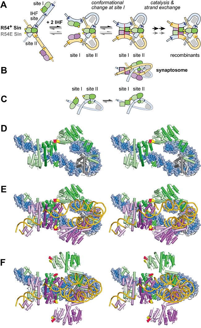
Fig. 9.

Proposed mechanism for cooperation between the F52/R54 interface and IHF in assembly of the site I tetramer within the synaptosome. The molecular models in (D), (E) and (F) are shown as stereo pairs. A. Proposed pathway for assembly of the synaptosome. Sin dimers in the ‘closed’ conformation are shown as ovals; dimers in the ‘open’ conformation, as in the site I synaptic tetramer, are shown as squares. Residues that form the F52/R54 interface are represented by yellow circles, and IHF is represented by a grey rectangle. B. The synaptosome in (A) viewed from below (i.e. rotated 90°). This is a cartoon representation of the molecular model in (E). C. Proposed looping interaction, mediated by the F52/R54 interface, between Sin dimers bound at sites I and II within the same resF site, shown out of the context of the synaptosome for clarity. Each cartoon is half of the model shown above it in (A), viewed from below (as in B). We suggest that the looping interaction stabilizes an ‘open’ conformation of the dimer at site I (squares) relative to the ‘closed’ conformation (ovals). A molecular model of the right-hand cartoon is shown in (D). D. Molecular model of the proposed looping interaction; this is one-half of the complete synaptosome model shown in (E). Two Sin dimers bound at the same resF site interact through the pseudo-symmetric F52/R54 interface as seen in the Sin site II crystal structure (pdb: 2R0Q). The site I dimer is in an ‘open’ conformation, as shown in Fig. 8B. The DNA is in spacefill, and the Sin dimers (pale/dark green) and IHF heterodimers (grey) are in cartoon representation; the side-chains of Sin residues F52 (yellow) and R54 (red) are highlighted in spacefill. E. Molecular model of the synaptosome incorporating the F52/R54 interface (shown in cartoon form in B). This model is essentially equivalent to fig. 7C of Mouw et al. (2008), except that all four catalytic domains in the site I synaptic tetramer were modelled by fitting segments of the Sin structure onto the γδ resolvase co-ordinates (cf. Fig. 8C here). The modelled synaptosome can be viewed as comprising two identical resF loops, held together by NTD interactions at site I, and CTD interactions at site II. The ‘back’ loop is as shown in (D); in the ‘front’ loop, the Sin dimers (lilac/purple) and the DNA (gold) are in cartoon representation (the IHF is omitted for clarity). Sin subunits at sites I and II make contact through the crystallographic F52/R54 interface, highlighted in spacefill (F52, yellow; R54, red). In order to create this interface, a conformational adjustment was made to the crystallographic site II tetramer: the NTDs were rotated towards the site I tetramer by straightening the kink in the E helix (of the pale green and lilac subunits). The positions of the regulatory site DNAs (relative to the site I DNAs) are slightly different from those shown in (F). F. The original molecular model of the synaptosome made by rigid body docking of known crystal structures, exactly as shown as in fig. 7A and B of Mouw et al. (2008) except that the IHF in the ‘front’ loop has been omitted for clarity. Note that residues F52 (yellow) and R54 (red) in the Sin site II tetramer are distant from their potential partners in the site I tetramer. The site I tetramer here is the γδ resolvase structure (and not the modelled Sin tetramer shown in E). γδ resolvase residues K54 (yellow) and E56 (red), which correspond to F52 and R54 in Sin, are highlighted (see Fig. 1D and Fig. S1). The particular conformation of the Sin NTDs seen in the site II tetramer may result from crystal packing forces.
