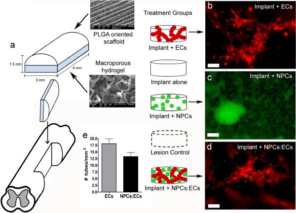
Figure 1. Implant design.
(a) Two component implant includes an outer PLGA oriented scaffold and an inner PEG/PLL macroporous hydrogel. (b) Live image of DiI-labeled rat ECs (red) cultured on a macroporous gel for one day. (c) Live image of GFP-positive rat NPCs (green) cultured on a macroporous gel for seven days. (d) Live image of DiI-labeled rat ECs (red) and GFP-positive rat NPCs (green) cultured on a macroporous gel for one day. Scale bar in (b–d) is 100 μm. (e) The number of EC tubes in the implant plus ECs and implant plus NPCs:ECs groups implanted into the hemisected spinal cord.

