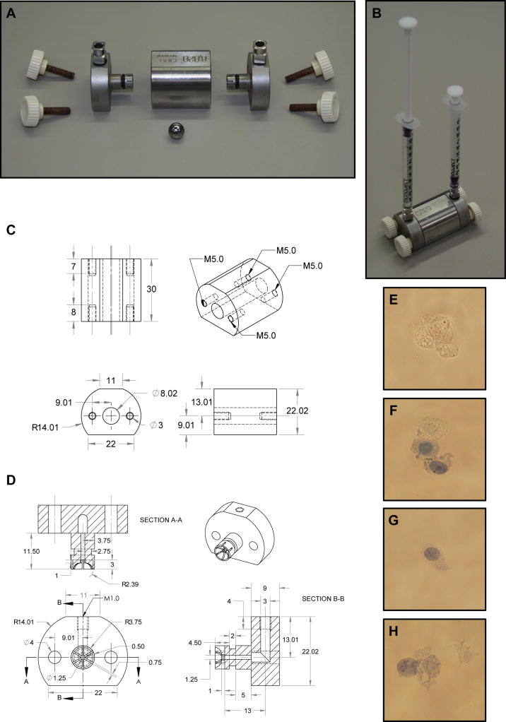
Figure 2.
Schematic diagram of a Balch homogenizer. (A) Balch homogenizer components include a stainless steel central chamber, two stainless steel end-caps with 6.35 mm, long threaded square body female luer hubs inserted through rubber o-rings, four 25 mm M5 threaded thumb screws and a tungsten carbide ball. (B) The Balch homogenizer is constructed while submerged in water and air is evacuated prior to use. Fluid is then passed into the Balch homogenizer chamber using 1 cc syringes attached to the luer adapters. (C) Schematic diagram of the Balch homogenizer central chamber. All measurements are in millimeters. (D) Schematic diagram of the Balch homogenizer end- caps with all measurements in millimeters. Rubber O-rings must be placed into the grooves on the end-cap insert shafts to properly seal the chamber. Different luer adapters may be attached to the threaded end-caps allowing a wide variety of input sources. (E) 3T3 MEF WT cells prior to homogenization show complete exclusion of trypan blue. (F) Cells passed through an 8 μm gap show partial disruption. One cell completely excludes trypan blue while the others show varying inclusion. (G) Cells passed through a 7 μm gap show good disruption. Trypan blue readily enters the cell while the plasma membrane and cellular structure is largely intact. Further, no membrane or nuclear debris is found within the supernatant. (H) Cells passed through a 4 μm gap show signs of excessive homogenization. Nuclei are partially disrupted and separated from cell bodies while cellular debris may be seen within the supernatant.

