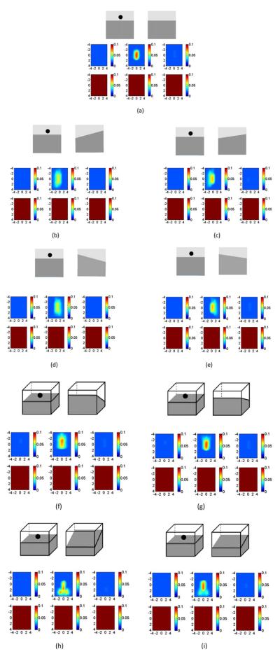
Fig. 7.
Reconstructed absorption maps of a target located at (x,y,z) =(0,0,0.9 cm). The first-and second-layer interfaces of both the target and the reference site were positioned at 1.5 cm depth. The interface at the target site has a zero-degree tilting angle. (a) to (i) sequentially show the absorption maps of the target with a target–reference layer tilting angle mismatch of (a) 0 deg, (b) 10 deg, (c) 5 deg, (d) −10 deg, and (e) −5 deg in the x direction, and of (f) 10 deg, (g) 5 deg, (h) −10 deg, and (i) −5 deg mismatch in the y direction. Optical properties of both the reference and target sites are μa1=0.02, , μa2=0.1, and The top picture of each part shows the position of the second layer and the target, and bottom picture shows the reconstructed absorption map.

