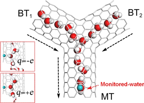
Fig. 1.
A schematic snapshot of the simulation system in side view (xz plane). The Y-SWNT features a main tube (MT) and 2 branch tubes (BT1, BT2) positioned in the same plane (the xz plane). The angle between each 2 neighboring SWNTs is 120°. Small angular changes do not affect the results. The SWNTs are represented by gray lines (and the positive direction of each nanotube is shown by the dashed arrowheads). Water molecules are shown with oxygen in red and hydrogen in gray. Water molecules outside the nanotubes are omitted in the figure. The green sphere represents the imposed charge. The water molecule facing the external charge is referred to as monitored water. The lengths of MT, BT1, and BT2 are 1.44 nm, 1.21 nm, and 1.21 nm, respectively. (Insets) Close-ups for the typical configurations of the monitored water and its neighboring water molecules: q = −e (Upper) and q = +e (Lower).

