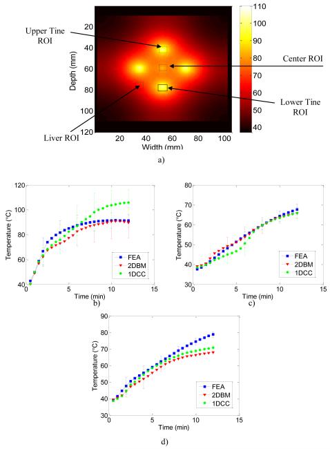
Figure 8.
FEA temperature images illustrating the regions of interest (ROI) over which the temperature estimates obtained using FEA and US simulations based on 1D CC and 2D BM algorithms were compared in Figure 8 a). Quantitative comparisons of the temperature estimated from ultrasound simulation using the 1D CC and 2D BM based temperature estimation algorithms using the calibration curve. The blue curve denotes the FEA computation, the red curve 2D BM and the green curve 1D CC results. Displacement data was accumulated from radiofrequency echo data acquired every 6 seconds for ROI’s at the b) tine (left side), c) simulated liver (right side) and at the d) center. The errorbars are shown only for limited estimates to reduce the clutter in the graph.

