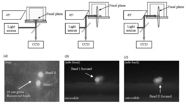
Fig. 2.
(a) A top view experimental setup and a fluorescent image showing two 16 μm diameter fluorescent beads, (b) a side view experimental setup when the focal plane is placed on the front bead (bead I), and its fluorescent image, and (c) when it is on the next bead (bead II) and its fluorescent image

