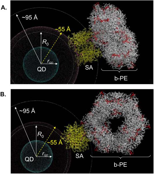
Figure 5. Models of the QD-b-PE conjugate structure/conformation.
(A) b-PE is parallel to the QD surface (θQD:b-PE = 0°), and (B) b-PE fully extended away from the QD (θQD:b-PE = 90°). Central QD with radius of ~29 Å (rQD) shown in blue is surrounded by a crimson shell of ~25 Å thickness representing the DHLA-PEG-biotin. The intermediary Streptavidin (SA) protein is shown in yellow with biotin-binding sites highlighted in purple. The b-PE ring structure is shown in white with the multiple chromophores highlighted in red. The inner concentric white circle corresponds to the R0 (53 Å) for the 540 nm-QD-b-PE assembly. The 2nd outer white circle is a visual distance marker set at ~95 Å from the QD center and represents the closest approach of the b-PE to the QD.

