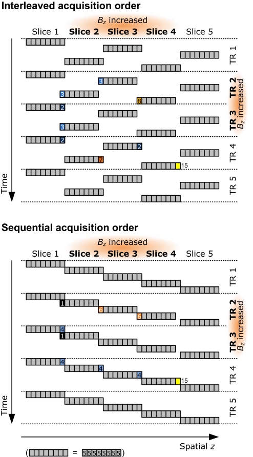
Fig. 4.
Emergence of transients. Transient signal components arise when Bz takes on a new value. This schematic shows the emergence of transients in the uniform phantom, for interleaved (Upper) and sequential (Lower) slice acquisition order. Bz is temporally increased during the second and third TR, in the three central slices of a stack of five slices; each slice has been divided into eight fractions (gray squares). The signal changes are color- and number-coded: light to dark blue colors illustrate signal losses, orange to yellow represent signal gains. Numbers indicate magnetization values (baseline = 5 units). Gray areas remain unchanged. The schematic ignores most details, such as a realistic excitation profile. It assumes that the available longitudinal magnetization is completely excited and linear, and the maximum excitable magnetization is considered to be at least 15 units. It shows clearly that even when Bz changes in several adjacent slices (slice 3 is surrounded by equally affected slices), transients, which depend on the acquisition order, occur. The horizontal axis is labeled spatial z to emphasize that the apparent position generally differs (slightly) from the actual z because of Bz changes. The shifted slice positions indicate the apparent slice positions caused by the increase in ΔBz. Because the excitation profile is infinitely steep and all available magnetization is always excited, the transients in the schematic last for only one time point.

