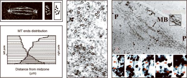
Fig. 2. Localization of KLP61F Crosslinkers.
Top left panel: Deconvolved fluorescence microscopy of an anaphase B spindle in longitudinal (left micrograph) and transverse (right micrograph) section. There are ~10 ipMT bundles per spindle (cartoon). Lower left and center panels: Organization of MTs within a single ipMT bundle from an anaphase B spindle (lower left) based on MT tracking from EMs (center). There are approximately 30 MTs emanating from each pole that overlap antiparallel. Right panel: ImmunoEM using gold anti-KLP61F labeling showing KLP61F all along an ipMT bundle (MB, upper micrograph) running from pole (P) to pole, where it may form electron dense MT-MT crosslinks (lower micrograph). See Brust-Mascher et al. [2004], Sharp et al. [1999a].

