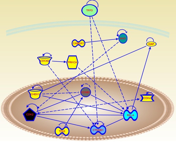
Figure 7.
Schematic representation of the signaling network of differentially expressed proteins. The figure was created using Ingeniuty and shows the connectivity between nodes (i.e. TCP1 and CDC42) and hubs (i.e. CCNB1, CTNNB1 and RELA). Solid lines indicate direct interaction. Dashed lines indicate indirect interaction. Arrows indicate stimulation. Bars indicate inhibition.

