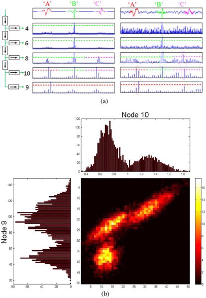
Fig. 2.
(a) Sparse representation of sample events from three units, “A,” “B,” and “C” in the noiseless (middle) and noisy (right) neural trace for five wavelet decomposition levels indicated by the binary tree (left). First level high-pass coefficients (node 2) are omitted as they contain no information in the spectral band of spike waveforms. Sensing thresholds are set to allow only one feature/event to survive in a given node. In this case, it is a local average of 32/2j coefficients. For example, nodes 4 and 6 can either be used to mark events from unit “B,” while node 9 can be used to mark events from unit “A.” When noise is present (right), the sensing threshold also serves as a denoising one. (b) 1-D and 2-D joint distributions of wavelet features for nodes 9 and 10 for the three units over many spike occurrences from each unit showing three distinct clusters. These projections can be used when spikes from different units result in identical sparse representations in a particular node (e.g., node 10). This can be used to resolve the ambiguity provided that these units were not already discriminated in earlier nodes.

