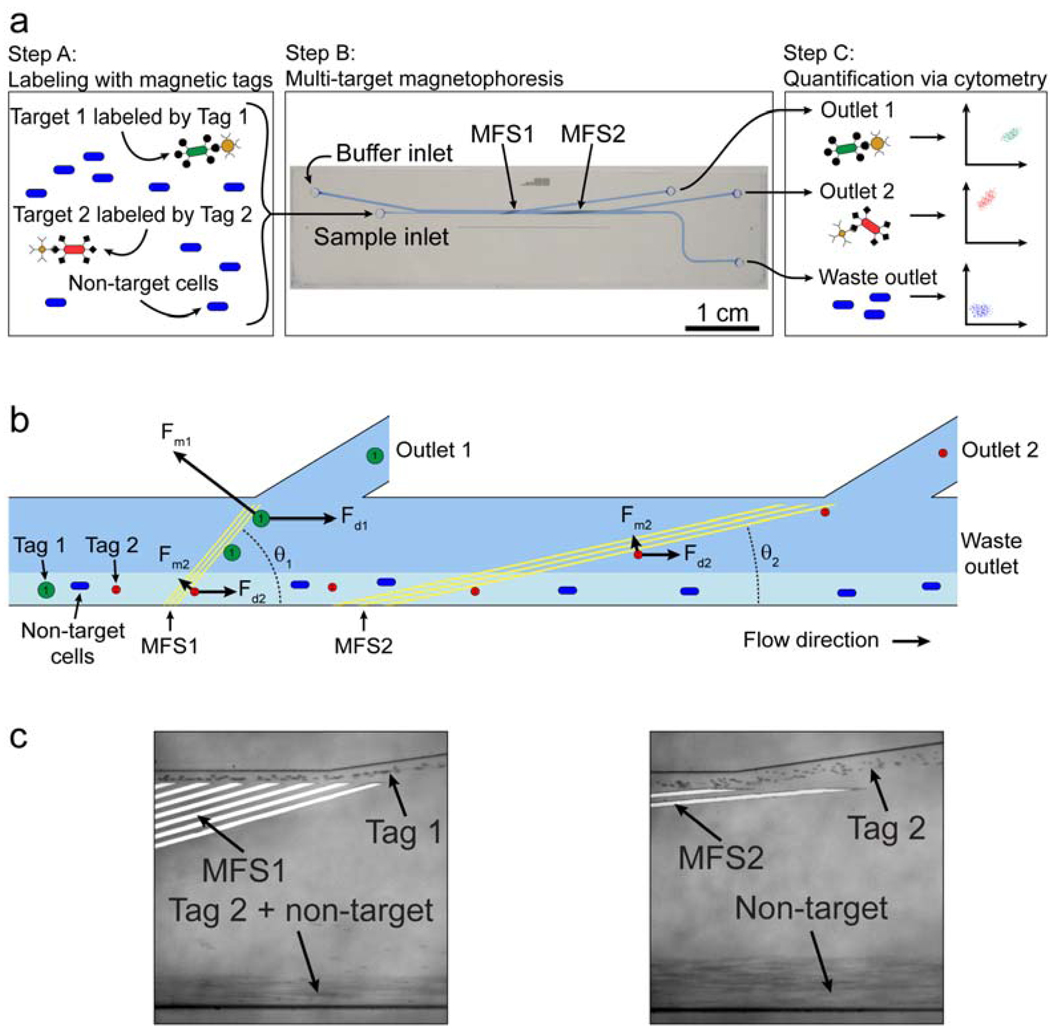
Figure 4.
MT-MACS separation architecture. a) The separation process. Step A: The sample contains an excess of non-target cells and two different target cell types, which are labeled with two different magnetic tags via specific surface markers. Step B: The sample is continuously pumped into the device, where the two target cell types are sorted into spatially segregated, independent outlets at regions of high magnetic field gradient generated by two sets of microfabricated ferromagnetic strips (MFS1 and MFS2). Step C: The eluted fractions from each outlet are analyzed via flow cytometry. b) A free-body diagram showing the balance of forces at the MFS structures. At MFS 1 (θ1 =15°), tag 1-labeled cells are deflected and elute through outlet 1 because Fm1>Fd1sin(θ1) . This is not the case for tag 2-labeled target 2 cells, which are instead deflected at MFS 2 (θ2 =5°), where Fm2 >Fd2 sin(θ2) and elute through outlet 2. Non-target cells are not deflected by either MFS and elute through the waste outlet. c) Optical micrographs (100X magnification) of tags being separated at the two MFS structures at a total flow rate of 47 ml/hr (sample = 5 ml/hr, buffer = 42 ml/hr). Tag 1 is deflected at MFS 1 (left), while tag 2 is deflected by MFS2 (right). Figure taken from Adams et al.35 with permission of the authors. © PNAS 2008

