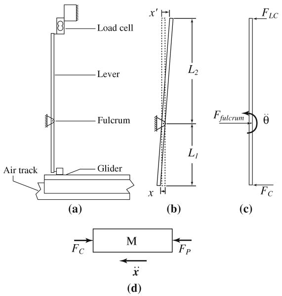
Fig. 2.
Schematic diagram of the lever, load cell, and air-bearing sled showing a components, b relevant dimensions (the dashed line shows the undeflected position of the lever), c free-body diagram of the lever showing applied horizontal forces, and d free-body diagram of the sled showing applied horizontal forces

