
Figure 4.
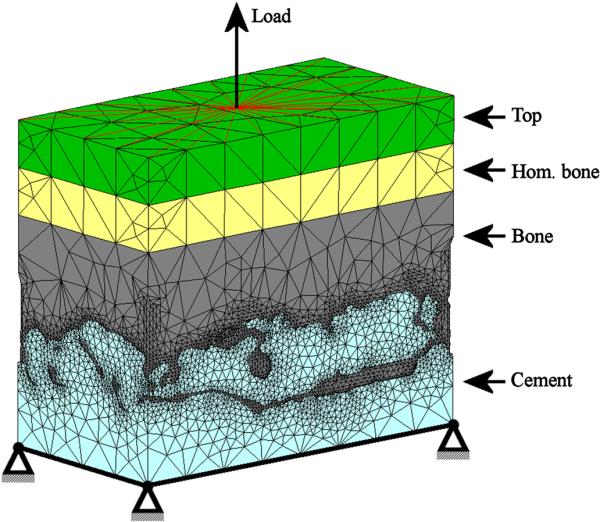
The cement model was fixed in all three directions at the bottom plane. A tensile load, representing the applied stress in the experiment, was applied to a single node at the top plane. All other nodes in the same plane were connected to the loaded node with rigid links to prevent the top plane from tilting, while displacements in the transverse and axial direction were allowed. The top and homogeneous bone layers both had a thickness of 1mm.