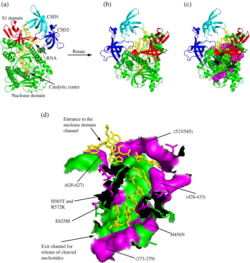
Figure 1. Distribution of Variant Residues in the Nuclease Domain Channel of RNase R.
All panels were generated using PyMOL (DeLano, W. L. The PyMOL Molecular Graphics System (2002). DeLano Scientific, San Carlos, CA. CA.[Online.] http://www.pymol.org) based on the crystal structure of RNase II14 (PDB code: 2IX1). (a) A cartoon representation of RNase R clearly showing the path that the RNA takes between the cold-shock and S1 domains into the nuclease domain. The cold-shock domains are colored in cyan and blue for CSD1 and CSD2, respectively, the nuclease domain is green with the catalytic magnesium ion represented by an orange sphere and the S1 domain is red. The RNA substrate is shown as yellow sticks. (b) An alternative perspective of RNase R obtained by rotation of panel (a). Coloring is the same as in panel (a). (c) The same as panel (b) with residues comprising the nuclease domain channel wall shown in a surface representation. Residues that are conserved between RNase R and RNase II remain in green and residues that differ are in magenta. (d) An enlarged surface representation of the residues which form the nuclease domain channel wall. As in panel (c), residues that are conserved between RNase R and RNase II are shown in green and residues that differ are in magenta. (The black areas are where amino acids have been removed to allow visualization of the channel). The approximate positions of the RNase R mutants constructed in this study are indicated. For orientation purposes, the entrance and exit of the channel are labeled.

