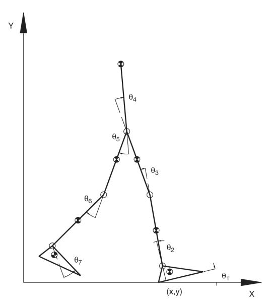
Fig. 1.
Schematic of the seven-link, nine-DOF, sagittal-plane model of the human body. The vector q = [x, y, θ1, θ2, …, θ7] represents the generalized coordinates of the model. Generalized coordinates x, y, and θ1 specify the position and orientation of the right foot, which was the base segment of the model during the stance phase, with reference to the global frame (X, Y). Joint angles θi (i = 2, 3,…,7) specify the angles of the right ankle, right knee, right hip, left hip, left knee, and left ankle, respectively. On the right side, the direction of the rotation axes is along the positive Z-axis (laterally to the right), but for the left side of the body the joint axes were in the direction of the negative Z-axis (laterally to the left). The locations of the centers of mass, shown as the half-shaded circles, were based on regression equation (McConville et al., 1980). The positive X-axis is in the direction of forward progression, and the positive Y-axis is upwards.

