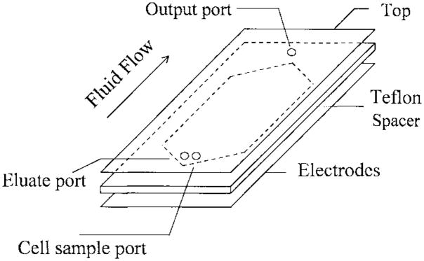
Fig. 1.
The schematic drawing of a dielectric-affinity separation chamber. In operation, the cell mixture sample is loaded into the chamber through the cell sample port. Then, appropriate electrical signals are applied to the DEP electrode array. Fluid flow is then started by pumping eluate through the eluate inlet port. The eluted cells are collected at the chamber output port at the other end of the chamber.

