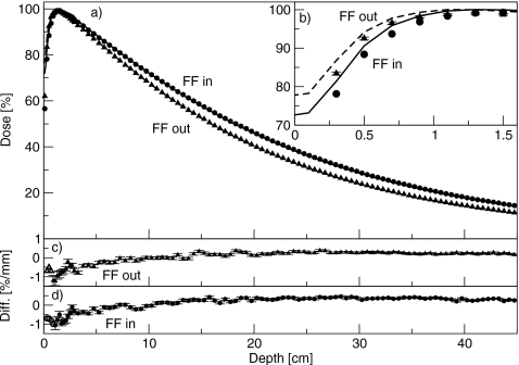
Figure 3.
(a) Percent-depth dose curves for the 6 MV beam, with and without the flattening filter. Lines are measured data and points are simulated data. Triangles are with the flattening filter out, and circles are with the flattening filter in. (b) Same results showing the comparison in the buildup region. Measured data are averaged over 0.2 cm and plotted at the center of the bin. Solid line is with the flattening filter in, and dashed lines are with the flattening filter removed. (c) and (d) Difference between simulated and measured results with the flattening filter out and in, respectively. Filled symbols (with error bars) represent a difference in percent, and open symbols (without error bars) represent a difference in millimeters.

