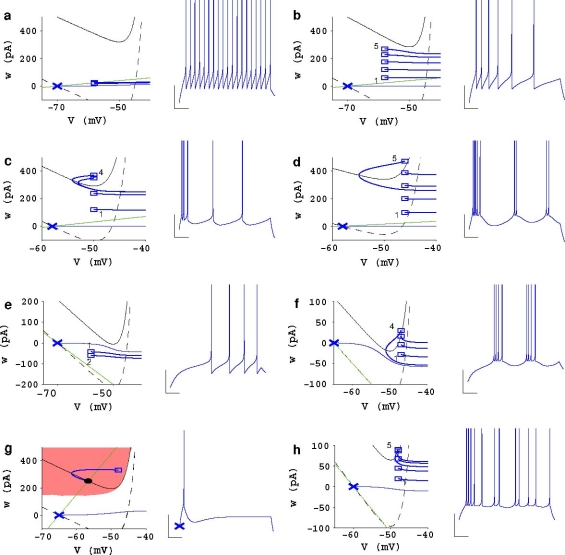
Fig. 4.
Phase plane representation of eight firing patterns. Firing patterns observed during a step current stimulation are: a tonic spiking, b adaptation, c initial burst, d regular bursting, e delayed accelerating, f delayed regular bursting, g transient spiking and h irregular spiking. The voltage traces are shown with a scale bar that corresponds to 100 and 20 mV. The graphs on the left show the traces in the phase planes as a trajectory (blue line) in the two state variables (V(t), w(t)). The w-nullcline (green) is a straight line, the V-nullcline before current stimulation is the curved dashed black line, and in the presence of stimulation, the curved solid line (black). The stable fixed point in (g) is indicated with a black, filled circle, and all the other symbols refer to the same convention as in Figs. 1 and 2. Comparing b with c illustrates that reset points jumping above the V-nullcline lead to initial bursting. Comparing c with d clarifies that regular bursting is obtained when the first broad reset generate a trajectory that passes below at least one of the previous reset points

