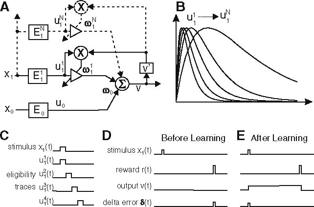
Fig. 8.

Filter bank approaches for CL and RL. a Schematic diagram of a filter bank implementation of ISO-learning. b Signal structure for signals u. c Serial compound representation: the simulated stimulus x(t) is split into traces u 1…n1(t) with only one non-zero value in time, which cover the duration until the reward is presented. Each of these traces has its own weight ω1…in1 which gets updated after each time step according to the delta error δ. d Using TD-learning the output is zero before learning, and thus the delta error δ peaks at the same time step the reward occurs. e After learning δ has moved forward in front of the reward, while the output υ arises with the stimulus and ends with the reward (Suri 2002; Wörgötter and Porr 2005)
