Figure 3.

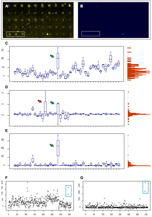
An example of a microarray with high background noise and poor spot quality. Plots showing results before and after applying the normalization procedure. A) and B) show a part of a microarray scanned in two channels; wavelength 488 (control with 6-Fam dye) and wavelength 532 (probes with Cy3 dye), respectively. The marked spot triplet in the bottom left corner shows a positive probe. Boxplots in C) show hybridization results of 42 detection probes with a positive probe indicated by green arrow. The probes are listed on the x-axis and their relative intensities on the right y-axis. On the left y-axis, a vertical histogram depicting the intensity distribution. The values are background subtracted detection probe channel signal intensities. D) shows the ratios of detection probe to adjusted control. Red arrow points a false positive. In E), the normalization described here is applied to the data, making positive signals better defined. F) and G) show all spots in the array before and after normalization, respectively. Marked spots in the top right corner indicate the positive probe.
