
Figure 1.
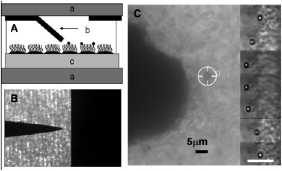
(A) Schematic of the 3DFM in pole-flat configuration: (a) a pair of coverglasses separated by ∼200 μm; (b) one pole tip bent toward the substrate, the “flat” fixed on upper glass labeled a; and (c) cells grown on Millicell membrane. (B) Top-view image of the pole-flat, thin-film magnetics. (C) Bright-field image (40×, 0.6 NA objective, and 1.5 image magnifier) of a 2.8 μm magnetic bead (tracking cursor in place) attached to beating cilia in the 3DFM. The pole tip is clearly visible 12 μm away. The inserted images on the right-hand side are time-series images (0.083 ms apart) of a 1 μm bead bound to beating cilia. A 5 μm scale bar is shown.