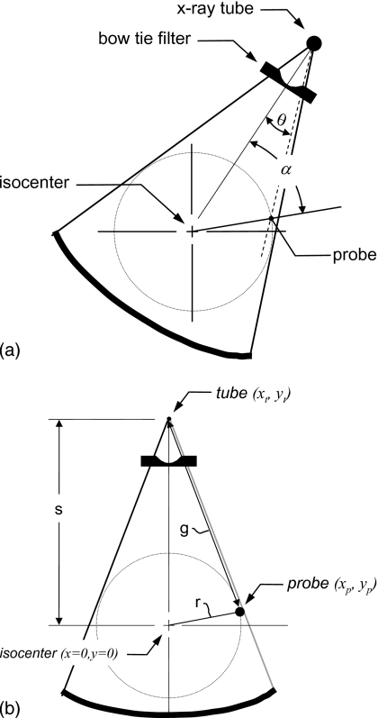
Figure 1.
The geometrical basis of the theoretical development of the proposed technique is illustrated. (a) The gantry angle α and the fan angle θ are illustrated. The gantry angle is defined as α=0 when the isocenter, probe, and source are coaligned and when the source is on the probe side of isocenter. For the fan angle, θ=0 in the center of the field of view (at isocenter). The bow tie filter function is symmetric about θ=0. (b) The distances s, r, and g are defined, along with the coordinates of the x-ray tube, x-ray probe, and isocenter. The source to isocenter distance is given by s, the radius from the isocenter to the x-ray probe is r, and the distance from the x-ray source to the x-ray probe is given by g. The values of s and r remain constant through gantry rotation as do the probe coordinates, while g changes along with the x-ray tube coordinates.

