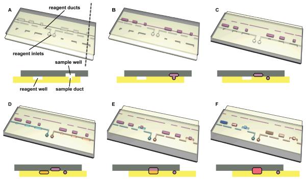
Figure 1.
Step-by-step 3D schematic drawings with cross-sectional views that describe the operation of a user-loaded SlipChip. (A) In the starting orientation, the two plates of the SlipChip are aligned such that the sample wells and sample ducts are aligned to form a continuous fluidic path, and the reagent wells and reagent ducts are offset. (B) The sample (purple) is loaded through the continuous fluidic path formed by overlapping sample wells (top plate) with sample ducts (bottom plate). (C) The device is slipped such that the reagent wells (bottom plate) and reagent ducts (top plate) are now aligned. (D) Reagents (blue and yellow) are loaded into the individual fluidic paths formed by overlapping reagent wells and sample wells. (E) The device is slipped a second time, and the sample wells from the top plate are exposed to the reagent wells of the bottom plate. (F) The pink well schematically shows a reaction taking place after mixing and incubation (see movie S1).

