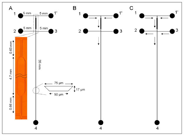
Figure 2.
(A) Schematic of microchip layout for on-chip labeling showing channel lengths, channel cross-sectional dimensions, and reservoir numbers. (Inset) Photomicrograph of the reaction channel. The reaction chamber is 300 μm wide on the bottom. Reservoirs 1 and 1′ are dye inlet and analyte inlet, respectively. Reservoirs 2–4 are waste, buffer inlet, and waste, respectively. (B) Schematic of flow during injection. Reservoirs 1 and 1′ were grounded, reservoirs 2 and 3 were floated, and reservoir 4 was maintained at +1600 V. The solution flow directions are indicated by arrows. (C) Schematic of flow in separation mode. Reservoirs 1, 1′ and 3 were grounded, reservoir 2 was at +700 V, and reservoir 4 was at +1600 V. The solution flow directions are indicated by arrows.

