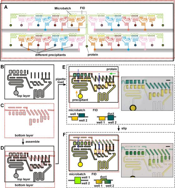
Figure 4.
Development of a composite SlipChip to combine microbatch and FID methods. (A) A schematic of the composite SlipChip. Multiple precipitants (pink, blue, red, and orange) and multiple volumes and equilibration times for mixing the protein (green) can be screened on the same SlipChip using both microbath and FID methods. B–F) A zoomed-in schematic of the area outlined in A showing the operation of the SlipChip. B) The top plate (contoured in black) contains wells for the protein and ducts for the precipitant (microbatch) and ducts for both the protein and precipitant (FID). C) The bottom plate (contoured in red) has ducts for the protein and wells for the precipitant (microbatch) and wells for both the protein and precipitant (FID). D) When the two plates are assembled, the fluidic path for the protein and the fluidic paths for the precipitants are formed to fill wells for both microbatch and FID methods. E) A schematic of solutions of protein (yellow) and precipitant (blue) filling wells after loading by pipetting. The cross-sectional view (taken along the blue dotted lines in the schematic) shows the relative position of the wells in the microbatch and FID methods before “slipping”. A microphotograph of the food dye experiment demonstrates loading of the wells. F) A schematic of how protein and precipitant wells from one plate can be connected after “slipping”. The cross-sectional view (taken along the dotted blue lines in the schematic) shows how the wells containing protein and wells containing precipitant are connected. In microbatch (left) the two wells are aligned with one another, in FID (right) the two wells are connected by a narrow channel. A microphotogragh of the food dye experiment demonstrates how the protein and precipitant are combined in both microbatch and FID methods.

