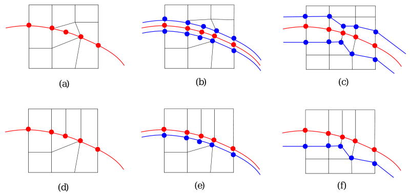
Fig. 12.
The pillowing technique. (a-c) show a “doublet” and (d-f) show an element whose two faces lie on the boundary, but the two faces are shared by two other elements. (a, d) - the original mesh, the red layer is the boundary shared by two materials; (b, e) - a parallel layer (the blue one) is created for the material with an element whose two faces lie on the boundary. Two layers are created in (b), but only one layer is created in (e); (c, f) - geometric flow is used to smooth the resulting mesh. The red layer is still on the boundary.

