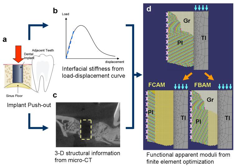
Figure 2. The in vivo finite element homogenization procedures for functional apparent moduli.
(a) The cylinder implant was pushed out (following the direction of the red arrow) from the jaw bone, and (b) the load-displacement relationship was recorded for calculating the interfacial stiffness (dash line, referred to the slope of the curve before the yielding point). (c) The three-dimensional (3-D) peri-implant structure was identified after removing the implant. (d) The finite element model was developed from projecting the peri-implant structure and interfacial information (microscopic model, upper panel) with the suspension boundary condition (pink marks on the peri-implant tissue border). In the optimizing model (lower panels), the peri-implant layer of interest was homogenized (yellow peri-implant regions), and the effective stiffness was calculated from the numerical approximation (to the microscopic model) under the implant loading condition (light blue arrows). Abbreviations: TI: titanium implant; PI: peri-implant tissue; Gr: granulation tissue in peri-implant area; FBAM: functional bone apparent modulus; FCAM: functional composite tissue apparent modulus

