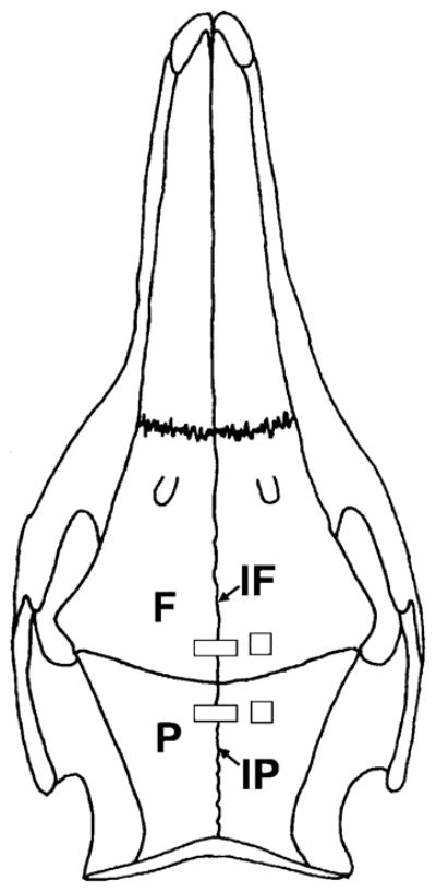
Fig. 1.

Schematic illustration of strain gage placement. Single-element (rectangle) strain gages were glued to the posterior interfrontal (IF) and the anterior interparietal (IP) sutures. The middle of the strain gage was positioned right above the suture and the suture was shielded from glue by placing a small strip of Teflon tape underneath the strain gage. Stacked rosette strain gages (square) were bonded to the right frontal (F) and parietal (P) bones.
