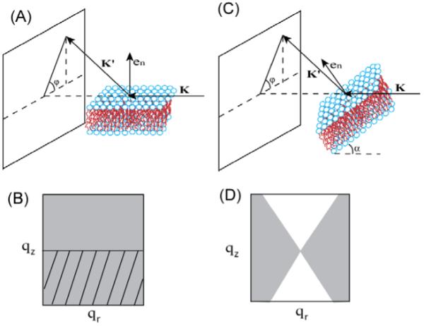
Figure 1.

(A) Grazing incident scattering and (C) transmission scattering experimental setup. K is the incident beam, K’ is the scattered beam, en is the normal to the bilayer tilted by angle α from the incident beam in (C). The gray regions in (B) and (D) represent the available reciprocal space corresponding to (A) and (C), respectively. The tilted lines in (B) indicate the region cut off by the silicon substrate.
