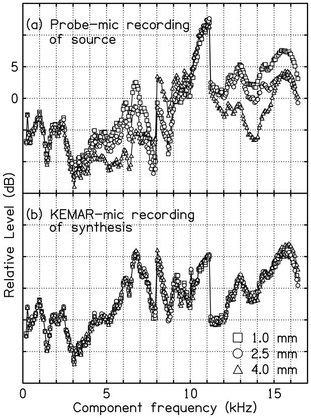
Figure 15.
Self-compensation in VRX. Part (a) shows the recorded power spectrum for three different positions of the probe-microphone tip in the ear canal of the KEMAR, 1.0, 2.5, and 4.0 mm. The recorded spectra were used to calibrate the system, leading to the recordings of part (b), measured at the KEMAR microphone (ear drum). Each vertical division is 5 dB. The discontinuities near 8 and 11 kHz reflect equalization EQ2 shown in Fig. 2.

