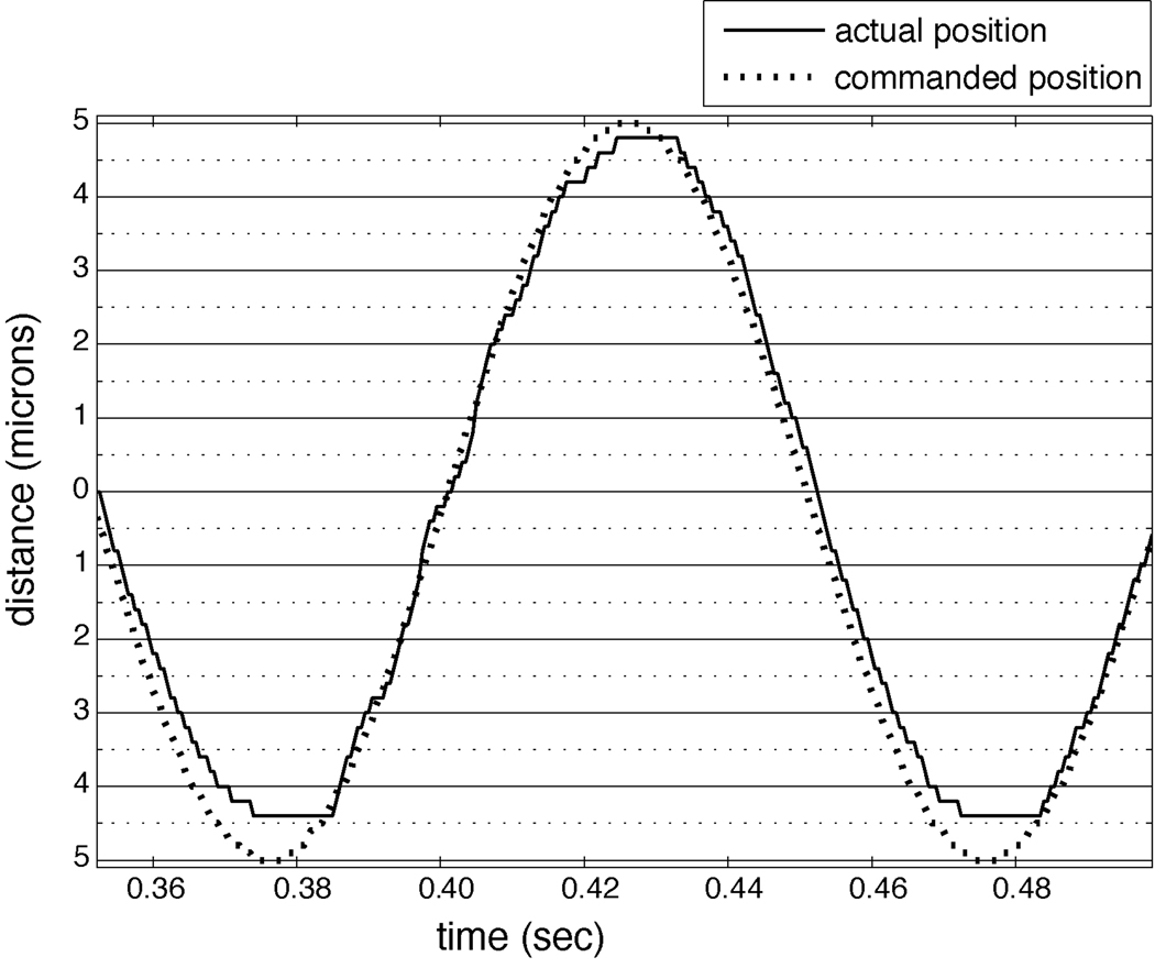
Figure 2.
Accuracy of the linear motor. Shown is the location of the linear motor’s shaft during part of a servo-controlled, 10 Hz sinusoidal stimulus with a 10 micron amplitude, used to simulate vibration. The dashed line indicates the commanded position of the shaft, and the solid line indicates the actual position. The error is less than one micron.

