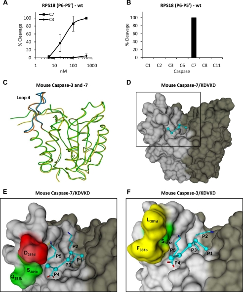
Fig. 4.
Caspase-7-specific cleavage of RPS18-delineated P6–P5′ undecapeptide and modeling of P5–P1 pentapeptide in substrate binding cleft of caspase-7 and -3. A, the P6–P5′ undecapeptide overlapping the caspase-7 cleavage site in RPS18 (RPS18(P6–P5′)-wt) was left untreated or treated with the indicated concentration of C7 or C3 for 1.5 h at 37 °C, and the generated fragments were analyzed by RP-HPLC for cleavage efficiency. B, RPS18(P6–P5′)-wt was incubated with a 250 nm concentration of the indicated caspases and analyzed by RP-HPLC. The activity of the recombinant caspase fractions was checked on their respective optimal tetrapeptide substrates (8) (data not shown). C, superposition of the structural model of mouse caspase-7 (green) and -3 (yellow) in ribbon representation. Loop 4 is in brown for caspase-7 and in blue for caspase-3. D, molecular model of KDVKD (cyan) in the substrate binding cleft of caspase-7 in surface representation. The black square delineates the active site of the caspase monomer and is enlarged for caspase-7 (E) and -3 (F) to indicate the S5-P5 lysine interactions. The dotted yellow line indicates a possible ion bridge between Asp278 and P5 lysine in caspase-7 (E). In D, E, and F, the p20 and p10 subunits are colored light and dark gray, respectively. Red, green, and yellow indicate negatively charged, uncharged polar, and hydrophobic residues, respectively. Molecular graphics were generated with YASARA and PovRay. The caspase-1 numbering convention is used (2, 43). Error bars indicate standard deviation of at least three independent experiments.

