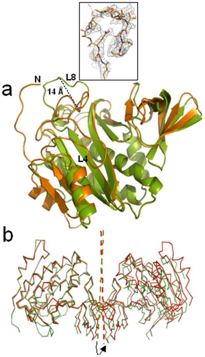
Figure 6. The asymmetric dimer.
(a) Superposition of cartoon representations of dhMtb-BirA subunit A (orange) and subunit B (green) exhibiting the structural differences in two subunits. Seven N-terminal residues and loop L4 are disordered in subunit B and have not been built. Maximum conformational differences in the two subunits are displayed in loop L8 with 14 Å shift measured at the apex of the loop. Inset shows the sigma weighed 2 Fo–Fc electron density map (gray mesh) contoured at 0.7σ around the L8 loop in subunit B of dhMtb-BirA (represented as sticks in atom type colors). (b) The dimeric molecule in the asymmetric unit of dhMtb-BirA (green) and hMtb-BirA (red) are shown after superposition of subunit A. The arrow indicates an anticlockwise rotation (7°) of the twofold axis that relates to the two monomers (indicated in the same color) required for subunit B of dhMtb-BirA to superpose on the corresponding subunit of hMtb-BirA.

