Abstract
The mechanisms of nerve conduction block induced by high-frequency biphasic electrical currents were investigated using a lumped circuit model of the myelinated axon based on Frankenhaeuser-Huxley (FH) model or Chiu-Ritchie-Rogart-Stagg-Sweeney (CRRSS) model. The FH model revealed that the constant activation of potassium channels at the node under the block electrode, rather than inactivation of sodium channels, is the likely mechanism underlying conduction block of myelinated axons induced by high-frequency biphasic stimulation. However, the CRRSS model revealed a different blocking mechanism where the complete inactivation of sodium channels at the nodes next to the block electrode caused the nerve conduction block. The stimulation frequencies to observe conduction block in FH model agree with the observations from animal experiments (greater than 6 kHz), but much higher frequencies are required in CRRSS model (greater than 15 kHz). This frequency difference indicated that the constant activation of potassium channels might be the underlying mechanism of conduction block observed in animal experiments. Using the FH model, this study also showed that the axons could recover from conduction block within 1 ms after termination of the blocking stimulation, which also agrees very well with the animal experiments where nerve block could be reversed immediately once the blocking stimulation was removed. This simulation study, which revealed two possible mechanisms of nerve conduction block in myelinated axons induced by high-frequency biphasic stimulation, can guide future animal experiments as well as optimize stimulation waveforms for electrical nerve block in clinical applications.
Keywords: Axon, electrical stimulation, high-frequency, nerve block, model
I. INTRODUCTION
Understanding the biophysics of nerve conduction block induced by electrical current will be very helpful in developing new methods to block peripheral nerves under different clinical conditions. For example, blocking pudendal nerve conduction during micturition could reduce urethral pressure and improve voiding efficiency in people with spinal cord injury [1]. Blocking peripheral nerves could also be used to treat chronic pain of peripheral origin [2], or to stop unwanted motor activity, such as muscle spasms, spasticity, tics and choreas [3]. Blocking nerves in a gradual manner starting with larger nerve fibers and progressing to smaller fibers [4]-[6] could be used to activate muscles in a physiological recruitment order and reduce muscle fatigue in functional neuromuscular stimulation.
A nerve block method employing biphasic electrical current will be more attractive than uniphasic current in chronic applications, since the biphasic stimulation causes less tissue damage due to electro-chemical reactions [7]. Animal experiments showed that high-frequency biphasic electrical current applied to peripheral nerves could block conduction of action potentials [1], [3], [8]-[11], [25], [28]. This nerve block was quickly reversible once the stimulation was removed. However, the mechanism of nerve conduction block induced by high-frequency biphasic electrical current is unknown. Since the biphasic electrical current can depolarize and hyperpolarize the nerve membrane alternately, it can not be assumed that the block is due to either membrane depolarization or hyperpolarization.
Our previous simulation studies [12], [13] in unmyelinated axons using the Hodgkin-Huxley model (HH model) have indicated that constant activation of potassium channels under the stimulation electrode, rather than inactivation of sodium channels, is the possible mechanism underlying the conduction block of unmyelinated axons. This type of block may also occur in amphibian (frog) myelinated axons where potassium currents are large and play a major role in regulating the generation of action potentials [16], [17]. It is uncertain if this mechanism is directly applicable to the mammalian myelinated axons where potassium currents are very small [14]-[16], but nevertheless play an important role in axonal excitability [26], [27]. In order to further elucidate the possible blocking mechanism in myelinated axons and investigate what role potassium channels play in conduction block, two axonal models of myelinated nerves were analyzed in this study. One model is the FH model [17] derived from frog nerves that describes myelinated nerve membrane dynamics with the presence of potassium channels. The second model is the CRRSS model [14], [16] that is derived from rabbit myelinated nerves and ignores potassium currents in membrane dynamics. By comparing the results from these two myelinated axon models, the hypothesis that constant activation of the potassium channels causes the nerve conduction block during high-frequency biphasic electrical stimulation was further tested.
In this study, we evaluated the ability of FH and CRRSS models to simulate the conduction block phenomena induced by high-frequency biphasic electrical currents, investigated the blocking mechanism for each model, and studied the recovery process of the myelinated axons after the termination of blocking stimulation. Results from this simulation study will further improve our understanding of the biophysics underlying the nerve conduction block induced by high-frequency biphasic electrical currents, which will guide future experiments on animals and provide better designs of the stimulation waveforms to block nerve conduction in many clinical applications [1]-[6].
II. METHODS
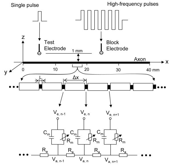
The nerve model used in this study is shown in Fig.1. A 40 mm long, myelinated axon is modeled with the inter-node length Δx = 100d (where d is the axon diameter). Each node (nodal length: L = 2.5 μm for FH model; L = 1 μm for CRRSS model) is modeled by a membrane capacitance (cm) and a variable membrane resistance (Rm). The ionic currents passing through the variable membrane resistance are described by FH model [16], [17] or by CRRSS model [14], [16] (see Appendix). Two monopolar point electrodes (with the indifferent electrode at infinity) are placed at 1 mm distance to the axon (Fig.1). One is the block electrode at the 25 mm location along the axon, where the high-frequency biphasic rectangular pulses (as shown in Fig.1) will be delivered. The other is the test electrode at the 5 mm location, which will deliver a uniphasic single pulse (pulse width 0.1 ms and intensity varying from 0.5 mA to 2 mA) to evoke an action potential and test whether this action potential can propagate through the site of the block electrode. The test electrode will always be a cathode (negative pulse), and the block electrode will always deliver biphasic pulses with the cathodal phase first.
Fig. 1.
Axon model to simulate conduction block induced by high-frequency biphasic electrical currents. The inter-node length Δx = 100d; d is the axon diameter. L is the nodal length. Each node is modeled by a resistance-capacity circuit based on FH or CRRSS model. Ra: axoplasm resistance; Rm: membrane resistance; Cm: membrane capacitance; Va: intracellular potential; Ve: extracellular potential; Single pulse: 0.5-2 mA intensity, 0.1 ms pulse width; High-frequency pulses: 0-10 mA intensity, 1-20 kHz for FH model, 1-40 kHz for CRRSS model.
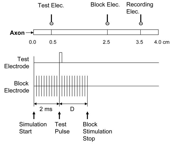
In order to study the recovery process after the termination of blocking stimulation, action potentials generated by the test pulse are monitored at the 3.5 mm location (see Fig.2, indicated by the recording electrode). The test pulse is always delivered at 2 ms after the start of the simulation, but the blocking stimulation stops at different times with a different delay (D) relative to the test pulse (see Fig.2). The purpose of terminating the blocking stimulation at different times is to see how it influences the propagation of the action potentials generated by the test pulse. This study is expected to elucidate how fast the axons of different diameters recover from the conduction block.
Fig.2.
Method to test the axon recovery from conduction block. The time delay (D) between the application of the test pulse and the stop of block stimulation was varied in different tests, so that the action potential evoked by the test pulse could arrive at the block electrode at a time when the axon recovery was at a different stage.
We assume that the axon is in an infinite homogeneous medium (resistivity ρe= 300 Ωcm). After neglecting the small influence induced by the presence of the axon in the homogeneous medium, the extracellular potential Ve,n at the nth node along the axon can be calculated by:
where Iblock(t) is the high-frequency biphasic rectangular pulse current delivered to the block electrode (at location x0 = 25 mm, z0 = 1 mm); Itest(t) is the single test pulse delivered to the test electrode (at location x1 = 5 mm, z1 = 1 mm).
The change of the membrane potential Vn at the nth node is described by:
where Vn = Va,n −Ve,n−Vrest; Va,n is the intracellular potential at the nth node; Ve,n is the extracellular potential at the nth node; Vrest is the resting membrane potential; ρi is the resistivity of axoplasm (100 Ωcm); cm is the capacity of the membrane (2 μF/cm2 for FH model; 2.5 μF/cm2 for CRRSS model); Ii,n is the ionic current at the nth node described by FH equations [16], [17] or by CRRSS equations [14], [16] (see Appendix).
The FH model was solved by Runge-Kutta method [18] with a time step of 0.001 ms. The CRRSS model was solved by an implicit trapezoidal integration method [19] with a time step of 0.0005 ms. The simulation always started at initial condition Vn = 0. The membrane potentials at the two end nodes of the modeled axon were always equal to the membrane potentials of their closest neighbors, which implemented the sealed boundary conditions (no longitudinal currents) at the two ends of the modeled axon. The simulations were performed with the temperature parameter set at 37 °C.
III. RESULTS
A. Conduction Block Induced by High-Frequency Biphasic Electrical Currents
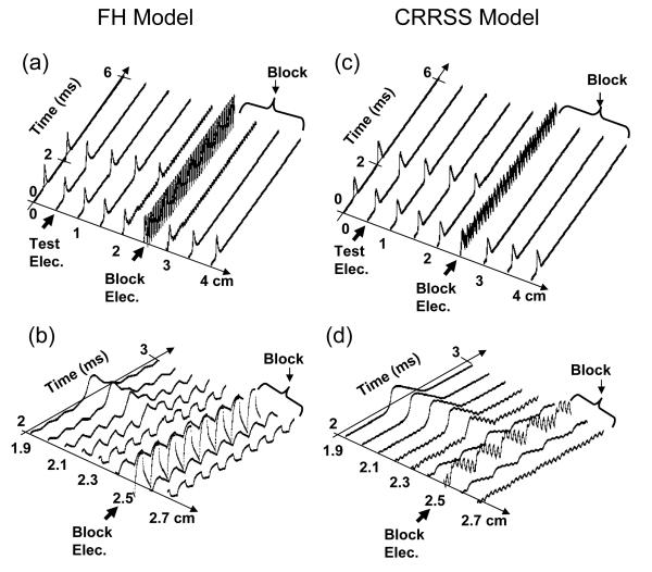
Fig.3 shows that both FH and CRRSS models can simulate the conduction block in myelinated axons induced by high-frequency biphasic electrical stimulation. Results shown in Fig.3 (a) and (b) are from FH model, while Fig.3 (c) and (d) are from CRRSS model. In Fig.3 (a) we can see that the high-frequency blocking stimulation at the block electrode generates an initial action potential that propagates in two directions. Then the high-frequency stimulation alternately depolarizes and hyperpolarizes the axon membrane without generating any action potential. At 2 ms after the blocking stimulation starts, the test electrode delivers a single pulse that generates another action potential propagating toward the block electrode. This action potential fails to propagate through the block electrode due to the presence of the high-frequency biphasic electrical stimulation. Fig.3 (b) is a detailed view of Fig.3 (a) to show the conduction block in a higher temporal-spatial resolution, where we can see the action potential gradually disappears when it approaches the block electrode. Similar to the FH model, CRRSS model can also simulate the conduction block [see Fig.3 (c)]. Fig3 (d) shows in a higher temporal-spatial resolution that the propagation of action potential in CRRSS model is gradually blocked as it approaches the block electrode.
Fig.3.
Conduction block simulated by FH model in (a) and (b), and by CRRSS model in (c) and (d). Axon diameter: 10 μm. Stimulation in (a) and (b): 8 kHz, 1.2 mA. The blocking threshold is 1 mA at 8 kHz for FH model. Stimulation in (c) and (d): 30 kHz, 0.7 mA. The blocking threshold is 0.65 mA at 30 kHz for CRRSS model.
Although both FH and CRRSS models can simulate the conduction block induced by high-frequency biphasic electrical currents, the effective frequency ranges to block axonal conduction are very different for these two models. At a temperature of 37 °C, conduction block can be observed when stimulation frequency is above 6 kHz using FH model (see our previous report) [20]. However, using CRRSS model we can only observe the conduction block when stimulation frequency is above 15 kHz. This large difference in blocking frequency between FH and CRRSS models indicates that different blocking mechanisms might occur in these two models.
B. Mechanism of Conduction Block
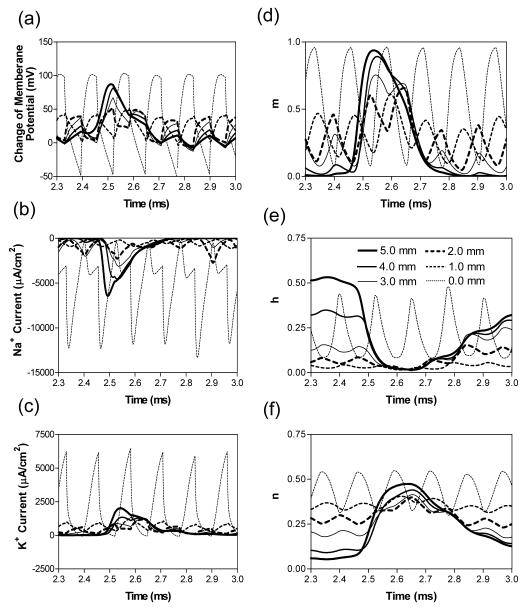
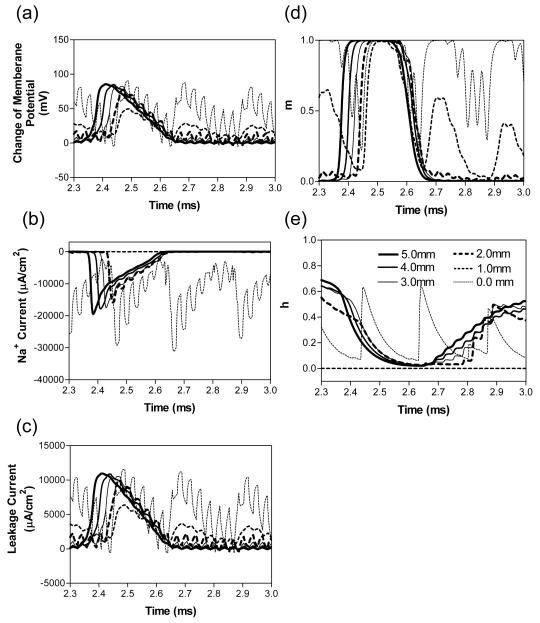
In order to understand the possible mechanisms of conduction block, we further investigated the propagation of membrane potentials, ionic currents, and activation/inactivation of the ion channels near the block electrode when nerve conduction block occurs as shown in Fig.3. Fig.4 shows the results for FH model, and Fig.5 for CRRSS model. Six consecutive nodes at distances of 0-5 mm from the block electrode are investigated (node at 0.0 mm is under the block electrode).
Fig.4.
FH Model: propagation of membrane potentials, ionic currents, and activation/inactivation of the ion channels near the block electrode when nerve conduction block occurs as shown in Fig.3 (a) and (b). The legends in (e) indicate the distances of each node to the block electrode (node at 0.0 mm is under the block electrode). m – activation of Na+ channels; h – inactivation of Na+ channels; n – activation of K+ channels.
Fig.5.
CRRSS Model: propagation of membrane potentials, ionic/leakage currents, and activation/inactivation of the ion channels near the block electrode when nerve conduction block occurs as shown in Fig.3 (c) and (d). The legends in (e) indicate the distances of each node to the block electrode (node at 0.0 mm is under the block electrode). m – activation of Na+ channels; h – inactivation of Na+ channels.
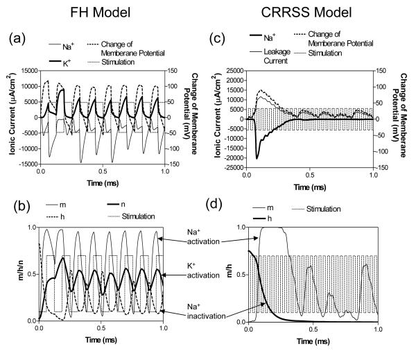
Fig.4 (a)-(c) shows that the action potential, sodium current, and potassium current are all propagating toward the block electrode, although their amplitudes are gradually attenuating. This propagation is completely abolished at the node (0.0 mm) under the block electrode, where axon membrane is alternately depolarized and hyperpolarized with large sodium and potassium currents. The behavior of the membrane potentials and ionic currents can be further explained by the activation/inactivation of the sodium and potassium channels as shown in Fig. 4 (d)-(f). As the action potential propagates toward the block electrode, the activation (m) of sodium channels also changes at each node and becomes oscillatory at the node under the block electrode [Fig.4 (d)]. Meanwhile, the inactivation (h) of sodium channels is kept at a high level (i.e. low value) at nodes of distances 1.0 mm and 2.0 mm to the block electrode [Fig.4 (e)]. Under the block electrode, the inactivation (h) of sodium channels becomes oscillatory. The combination of activation (m) and inactivation (h) of sodium channels [Fig.4 (d) and (e)] determines that the amplitude of the sodium current gradually attenuates at nodes close to the block electrode and eventually becomes a pulsed inward current at the node (0.0 mm) under the block electrode [Fig.4 (b)]. Therefore, FH model shows that the sodium channels are never completely blocked when conduction block occurs. However, FH model does show that the changes in potassium activation (n) induced by the action potentials gradually disappear at the nodes close to the block electrode [Fig.4 (f)] since the potassium channels become constantly activated at those nodes. The level of potassium channel activation is maximal at the node (0.0 mm) under the block electrode, which results in a large pulsed outward potassium current [Fig4 (c)]. This large outward potassium current opposes the large inward sodium current, which causes the node (0.0 mm) under the block electrode to become un-excitable leading to block of action potential propagation. Figs.6 (a) and (b) show how the node (0.0 mm) under the block electrode is driven by the high-frequency blocking stimulation into the un-excitable state. The stimulation waveform is also plotted on the background to show the timing. As shown in Fig.6 (b), after an initial action potential the potassium channels are activated (n is around 0.4) resulting in pulsed, outward potassium current [Fig.6 (a)]. Meanwhile, both activation (m) and inactivation (h) of sodium channels becomes oscillatory, which results in pulsed, inward sodium current [Fig.6 (a)]. However, during the depolarization phase [cathodal/negative pulse, see Fig.6 (a)] the potassium current is large enough to oppose the sodium current, which results in the node becoming un-excitable. This also explains why high-frequency blocking stimulation can not generate action potentials after the initial one [see Fig.3 (a)], even though it alternately depolarizes and hyperpolarizes the membrane. Therefore, FH model reveals that the conduction block induced by high-frequency biphasic electrical stimulation is due to the constant activation of potassium channels under the block electrode.
Fig.6.
Change of membrane potential, ionic currents, and activation/inactivation of the ion channels after the initial action potential as shown in Fig.3 at the node (0.0 mm) under the block electrode in FH model: (a) and (b); or at the node (1.0 mm) next to the block electrode in CRRSS model: (c) and (d). The stimulation waveform is re-scaled and plotted on the background to show the timing. m – activation of Na+ channels; h – inactivation of Na+ channels; n – activation of K+ channels.
A different blocking mechanism is revealed by the CRRSS model. Fig.5 shows the propagation of action potential, sodium/leakage currents, and activation/inactivation of sodium channels when conduction block occurs as simulated in Fig.3 (c) and (d). Although the action potential and the leakage current both propagate toward the block electrode with gradually attenuating amplitudes [Fig.5 (a) and (c)], the sodium current is completely blocked at the node (1.0 mm) next to the block electrode [Fig.5 (b)]. This block of sodium current is due to the complete inactivation (h) of sodium channels [see Fig.5 (e) where h is 0.0 at 1.0 mm node] even though activation (m) of sodium channels can still reach 1.0 [see Fig.5 (d)]. Therefore, in the absence of a potassium current the CRRSS model reveals that the conduction block is due to the inactivation of sodium channels at the node next to the block electrode. How the nodes next to the block electrode are driven by the high-frequency blocking stimulation into the un-excitable state is shown in Fig.6 (c) and (d) (note: the two nodes on both sides of the block electrode have the same membrane activity). After generating an initial action potential, the blocking stimulation keeps the sodium channels inactivated at the nodes next to the block electrode [h=0, see Fig.6 (d)], which blocks inward sodium current [Fig.6 (c)]. This also explains why the high-frequency blocking stimulation can not generate an action potential after the initial one [Fig.3 (c)], although it can repetitively depolarize the membrane at the node under the block electrode [Fig.5 (a)]. It is worth noting that the high-frequency biphasic stimulation does not hyperpolarize the membrane at the node under the block electrode in CRRSS model [Fig.5 (a)], but it does in FH model [Fig.4 (a)].
The blocking mechanisms as shown in Figs. 4-6 for both FH and CRRSS models are also observed at other stimulation intensities with different stimulation frequencies whenever the conduction block occurs. However, the blocking mechanism involving complete inactivation of sodium channels revealed by CRRSS model was not observed in FH model even at stimulation frequency above 15 kHz.
C. Axonal Recovery from Conduction Block
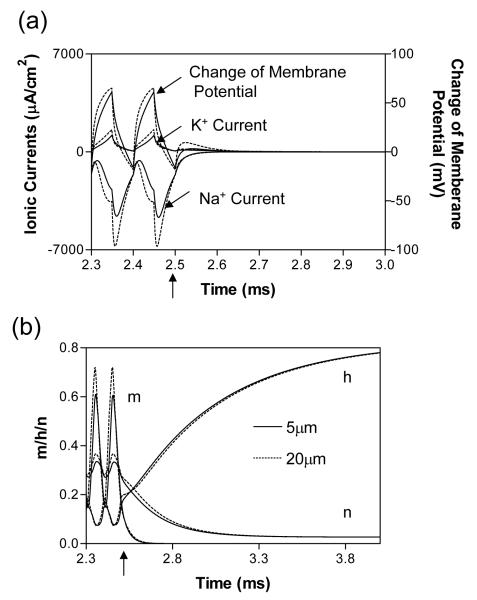
Fig.7 shows in the FH model the recovery of membrane potential, ionic currents, and activation/inactivation of ion channels at the node (0.0 mm) under the block electrode after termination of the blocking stimulation. The arrows on the time axis indicate the termination time (2.5 ms). Although the membrane potential, sodium and potassium currents recover within 0.1 ms after termination of the blocking stimulation [Fig.7 (a)], the full recovery of ion channels requires about 1 ms [Fig.7 (b)]. The recovery time for axons of different diameters (5-20 μm) is almost the same (Fig.7).
Fig.7.
Change of membrane potential, ionic currents, and activation/inactivation of the ion channels after the termination of block stimulation at the node (0.0 mm) under the block electrode in FH model. Data from axons of diameter 5 μm and 20 μm are both plotted in this figure for comparison. m – activation of Na+ channels; h – inactivation of Na+ channels; n – activation of K+ channels. Stimulation: 10 kHz, 1.2 mA for 5 μm axon, but 0.41 mA for 20 μm axon. The arrows on the time axis marked the time when block stimulation is terminated.
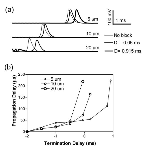
Fig.8 shows how propagation of action potentials is influenced at different stages during the recovery of axonal conduction. Fig.8 (a) shows that axons of different diameters (5, 10 and 20 μm) conduct action potentials from the test electrode to the recording electrode (see Fig.2) at different velocities. The axonal conduction can be delayed or blocked by terminating the blocking stimulation at different times. When the blocking stimulation is terminated with a delay (D) of −0.06 ms relative to the test pulse (i.e. terminated at 0.06 ms before the test pulse, see Fig.2), the action potential propagating in the 20 μm axon is maximally delayed while the 5 and 10 μm axons are only moderately delayed [see Fig.8 (a)]. But, if the termination delay (D) of the blocking stimulation is 0.915 ms, both 10 and 20 μm axons are blocked and only the 5 μm axon can conduct an action potential with a maximal delay [see Fig.8 (a)]. Fig.8 (b) shows how the propagation delays of action potentials in axons of different diameters (5, 10 and 20 μm) change with the termination delay (D) of the blocking stimulation. The larger axons are delayed more than the smaller axons, or blocked before the smaller axons. This is mainly due to the different conduction velocities, since action potentials in larger axons arrive at the block electrode earlier than smaller axons. The maximal propagation delays for axons of different diameters are between 150-250 μs [with difference less than 100 μs, see Fig.8 (b)], which are not changed proportionally with the axon diameter. This indicates that the time for axonal recovery from conduction block in different axons is almost the same (see Fig.7).
Fig.8.
Recovery from conduction block in FH model. (a). Propagation of action potentials in axons of different diameters are either delayed or blocked when the block stimulation is terminated at a different time [with a different delay (D) relative to the test pulse (see Fig.2)]. (b). Propagation delay of action potential changes with termination delay (D) of the block stimulation. Stimulation: 10 kHz, 1.2 mA.
IV. DISCUSSION
In this study, we investigated the possible mechanisms underlying axonal conduction block induced by high-frequency biphasic electrical currents in myelinated axons using both FH and CRRSS models. The FH model reveals that the constant activation of potassium channels at the node under the block electrode, rather than inactivation of sodium channels, causes axonal conduction block [Fig.4 and Fig.6 (a) and (b)]. The CRRSS model reveals a different mechanism where the complete inactivation of sodium channels at the nodes next to the block electrode causes the axonal conduction block [Fig.5 and Fig.6 (c) and (d)]. Due to the different blocking mechanism, the frequency ranges where the conduction block can be observed are very different for FH or CRRSS models. Axonal conduction block can be observed at stimulation frequencies greater than 6 kHz using FH model [20], but the frequencies have to be greater than 15 kHz using CRRSS model. This frequency difference between FH and CRRSS models can be explained by the different dynamics of sodium and potassium channels, since sodium channel can open and close much faster than potassium channels [see Fig.6 (b)].
Animal experiments [3], [8]-[11] at room temperature (around 25 °C) have shown that high-frequency biphasic electrical stimulation can block nerve conduction when stimulation frequency is greater than 3-5 kHz. Our study of nerve conduction block of myelinated fibers in cats [1] has demonstrated that stimulation frequency needs to be greater than 6 kHz if the temperature is around 35-37 °C. Our previous study using the FH model [20] revealed that a higher stimulation frequency was required at a high temperature. Since the blocking mechanism revealed by the FH model requires stimulation frequency greater than 6 kHz at 37 °C, it more likely reflects the nerve conduction block observed in animal studies at frequencies below 15 kHz [1], [3], [8]-[11]. Meanwhile, the blocking mechanism revealed by the CRRSS model is less likely involved in the nerve conduction block observed in the animal studies, since it requires a much higher stimulation frequency (greater than 15 kHz). Therefore, this study further indicates that the constant activation of potassium channels, rather than inactivation of sodium channels, is likely to be the underlying mechanism of axonal conduction block in myelinated axons induced by high-frequency biphasic electrical stimulation at frequencies below 15 kHz. The same blocking mechanism was also revealed in unmyelinated axons in our previous simulation studies [12], [13].
This study has shown that very different blocking mechanisms can be revealed by FH or CRRSS model. The ability of different models to simulate axonal conduction block induced by high-frequency biphasic electrical stimulation is determined by the membrane dynamics built into the different models. Due to the lack of potassium channels in CRRSS model, it can only simulate conduction block induced by inactivation of sodium channels at a relatively high frequency (greater than 15 kHz). A recent study using CRRSS model [25] claimed that nerve conduction block could be observed at frequencies above 50 kHz. Currently, it is still un-clear whether the blocking mechanism involving sodium inactivation might be involved in the nerve conduction block in the animal experiments [3], [8]-[10], [25], [28] when stimulation frequency is greater than 15 kHz. Although both FH and CRRSS models could successfully simulate axonal excitation [16], the CRRSS model failed to simulate the axonal block that was observed in animal studies at stimulation frequency between 5 kHz and 10 kHz [1], [3], [8]-[11]. This indicates that the CRRSS model has a limited ability to simulate nerve block due to its lack of potassium current.
The FH model is derived from a study of frog nerves [17], which include both sodium and potassium channels. The CRRSS model that is derived from studies of mammalian nerves (rabbit) [14] only includes sodium channels. However, another axonal membrane model that is derived from mammalian nerves (rat) does include both sodium and potassium channels [15]. A previous study using this model successfully simulated the axonal conduction block at stimulation frequencies between 5 kHz and 20 kHz, but the possible nerve blocking mechanism was not explored [25]. A recent study [3] using a newly developed human axonal model [24], which incorporated fast sodium current, persistent sodium current, and slow potassium current in a double cable model, demonstrated that nerve conduction block induced by high-frequency biphasic stimulation was caused by a steady-state depolarization along the axon. It is unfortunate that this study did not show the ionic currents and the gating parameters of different ion channels. We did not observe a steady-state depolarization in our simulation studies using either FH or CRRSS model. Another study [25] using a similar human axonal model also did not observe a steady-state depolarization, but instead revealed membrane potential oscillations between −188 mV and +120 mV during each stimulus cycle depending on the stimulation intensity and nodal locations. However, in order to show a mean depolarization along the axon, the membrane potential was averaged over each stimulus cycle [25]. A further investigation of the ability of different axonal models to simulate nerve conduction block is needed. Of course, any blocking mechanism suggested by simulation studies using models needs to be confirmed by neurophysiologic experiments using animals before it can be finally accepted. More evidence from either animal experiments or model analysis is needed to further verify the blocking mechanism and to discover any new mechanism.
Only high-frequency stimulation using biphasic pulses was analyzed in this simulation study. Blocking muscle contraction by electrical stimulation of peripheral nerves using high-frequency uniphasic pulses has also been reported [21]-[23]. However, the blocking mechanism for high-frequency uniphasic pulses might be different from the blocking action of high-frequency biphasic stimulation [13], since uniphasic pulses can only depolarize the axonal membrane under the block electrode. A further simulation study is needed to reveal the blocking mechanism for uniphasic pulses.
Conduction of action potentials or muscle contraction can be observed within 1 second after the termination of blocking stimulation in animal experiments [1], [3], [8]-[11], [25], [28] although no study actually measured the exact time for recovery from nerve block. This simulation study shows that the ion channels can recover in about 1 ms after the termination of blocking stimulation (see Fig.7). The maximal propagation delays for axons of different diameters (5-20 μm) are less than 0.25 ms [see Fig.8 (b)]. In this study the axonal recovery from conduction block was only investigated using FH model, since CRRSS model can not simulate the conduction block within the frequency range observed in animal experiments (greater than 3-5 kHz) [1], [3], [8]-[11]. Using the CRRSS model to study the axonal recovery from conduction block will reveal how fast the sodium channels can recover after they are completely inactivated. The recovery from conduction block can also be investigated using other membrane models [15].
Only a monopolar point electrode was used in this simulation study with a fixed electrode distance (1 mm) to the stimulated axon. More stimulation studies should be conducted to investigate the influence of different electrode configurations, which may include the bipolar/tripolar point electrodes or cuff electrodes since these electrode configurations are often used in both animal studies[1], [3], [8]-[11], [25], [28] and clinical applications [1]-[6]. New mechanisms of conduction block may be discovered by simulation studies using other electrode configurations.
This study revealed two different mechanisms underlying conduction block in myelinated axons induced by high-frequency biphasic electrical stimulation using FH and CRRSS models. Understanding biophysics of nerve conduction block can guide the design of future experiments on animals and optimize the stimulation waveforms for clinical applications to reversibly block the peripheral nerve conduction [1]-[6].
ACKNOWLEDGEMENT
This work is supported by the NIH under grants 1R01-DK-068566-01, 1R01-NS-045078 and 1P01-HD-39768-02.
APPENDIX
1 Axonal membrane dynamics in FH model
The ionic current Ii,n at nth node is described as:
where PNa (0.008 cm/s), PK (0.0012 cm/s) and PP (0.00054 cm/s) are the ionic permeabilities for sodium, potassium and nonspecific currents respectively; gL (30.3 kΩ−1 cm−2) is the maximum conductance for leakage current. VL (0.026 mV) is reduced equilibrium membrane potential for leakage ions, in which the resting membrane potential Vrest (−70 mV) has been subtracted. [Na]i (13.7 mmole/l) and [Na]o (114.5 mmole/l) are sodium concentrations inside and outside the axon membrane. [K]i (120 mmole/l) and [K]o (2.5 mmole/l) are potassium concentrations inside and outside the axon membrane. F (96485 c/mole) is Faraday constant. R (8314.4 mJ/K/mole) is gas constant. m, h, n and p are dimensionless variables, whose values always change between 0 and 1. m and h represent activation and inactivation of sodium channels, whereas n represents activation of potassium channels. p represents activation of non-specific ion channels. The evolution equations for m, h, n and p are the following:
and
where T is the temperature in °Kelvin (310 °Kelvin = 37°C). The initial values for m, h, n and p (when Vn = 0 mV) are 0.0005, 0.0268, 0.8249 and 0.0049 respectively.
2. Axonal membrane dynamics in CRRSS model
The ionic current Ii,n at the nth segment is described as:
where gNa (1445 kΩ−1cm−2) and gL (128 kΩ−1cm−2) are the maximum conductance for sodium and leakage currents respectively; VNa (115 mV) and VL (−0.01 mV) are reduced equilibrium membrane potentials for sodium and leakage ions, in which the resting membrane potential Vrest (−80 mV) has been subtracted. m and h are dimensionless variables, whose values always change between 0 and 1, representing activation and inactivation of sodium channels. The evolution equations for m and h are the following:
and
where T is temperature (37°C). The initial values for m and h (when Vn = 0 mV) are 0.003 and 0.75 respectively.
REFERENCES
- [1].Tai C, Roppolo JR, de Groat WC. Block of external urethral sphincter contraction by high frequency electrical stimulation of pudendal nerve. J. Urol. 2004;Vol.172:2069–2072. doi: 10.1097/01.ju.0000140709.71932.f0. [DOI] [PubMed] [Google Scholar]
- [2].Nashold BS, Goldner JL, Mullen JB, Bright DS. Long-term pain control by direct peripheral-nerve stimulation. J. Bone and Joint Surg. 1982;Vol.64A:1–10. [PubMed] [Google Scholar]
- [3].Kilgore KL, Bhadra N. Nerve conduction block utilising high-frequency alternating current. Med. Biol. Eng. Comput. 2004;Vol.42:394–406. doi: 10.1007/BF02344716. [DOI] [PubMed] [Google Scholar]
- [4].Baratta R, Ichie M, Hwang SK, Solomonow M. Orderly stimulation of skeletal muscle motor units with tripolar nerve cuff electrode. IEEE Trans. Biomed. Eng. 1989;Vol.36:836–843. doi: 10.1109/10.30809. [DOI] [PubMed] [Google Scholar]
- [5].Fang ZP, Mortimer JT. A method to effect physiological recruitment order in electrically activated muscle. IEEE Trans. Biomed. Eng. 1991;Vol.38:75–179. doi: 10.1109/10.76384. [DOI] [PubMed] [Google Scholar]
- [6].Tai C, Jiang D. Selective stimulation of smaller fibers in a compound nerve trunk with single cathode by rectangular current pulses. IEEE Trans. Biomed. Eng. 1994;Vol.41:286–291. doi: 10.1109/10.284949. [DOI] [PubMed] [Google Scholar]
- [7].Agnew WF, McCreery DH. Neural Prostheses: Fundamental Studies. Prentice Hall; Englewood Cliffs, NJ: 1990. [Google Scholar]
- [8].Reboul J, Rosenblueth A. The action of alternating currents upon the electrical excitability of nerve. Am. J. Physiol. 1939;Vol.125:205–215. [Google Scholar]
- [9].Rosenblueth A, Reboul J. The blocking and deblocking effects of alternating currents on nerve. Am. J. Physiol. 1939;Vol.125:251–264. [Google Scholar]
- [10].Tanner JA. Reversible blocking of nerve conduction by alternating-current excitation. Nature. 1962;Vol.195:712–713. doi: 10.1038/195712b0. [DOI] [PubMed] [Google Scholar]
- [11].Bowman BR, McNeal DR. Response of single alpha motoneurons to high-frequency pulse train: firing behavior and conduction block phenomenon. Appl. Neurophysiol. 1986;Vol.49:121–138. doi: 10.1159/000100137. [DOI] [PubMed] [Google Scholar]
- [12].Tai C, de Groat WC, Roppolo JR. Simulation analysis of conduction block in unmyelinated axons induced by high-frequency biphasic electrical currents. IEEE Trans. Biomed. Eng. 2005;Vol.52:1323–1332. doi: 10.1109/tbme.2005.847561. [DOI] [PMC free article] [PubMed] [Google Scholar]
- [13].Tai C, de Groat WC, Roppolo JR. Simulation of nerve block by high-frequency sinusoidal electrical current based on the Hodgkin-Huxley model. IEEE Trans. Neural Syst. Rehab. Eng. 2005;Vol.13:415–422. doi: 10.1109/TNSRE.2005.847356. [DOI] [PubMed] [Google Scholar]
- [14].Chiu SY, Ritchie JM, Rogart RB, Stagg D. A quantitative description of membrane currents in rabbit myelinated nerve. J. Physiol. (Lond) 1979;Vol.292:149–166. doi: 10.1113/jphysiol.1979.sp012843. [DOI] [PMC free article] [PubMed] [Google Scholar]
- [15].Schwarz JR, Eikhof G. Na currents and action potentials in rat myelinated nerve fibres at 20 and 37°C. Pflugers Arch. 1987;Vol.409:569–577. doi: 10.1007/BF00584655. [DOI] [PubMed] [Google Scholar]
- [16].Rattay F, Aberham M. Modeling axon membranes for functional electrical stimulation. IEEE Trans. Biomed. Eng. 1993;Vol.40:1201–1209. doi: 10.1109/10.250575. [DOI] [PubMed] [Google Scholar]
- [17].Frankenhaeuser B, Huxley AF. The action potential in the myelinated nerve fibre of Xenopus Laevis as computed on the basis of voltage clamp data. J. Physiol. (Lond) 1964;Vol.171:302–315. doi: 10.1113/jphysiol.1964.sp007378. [DOI] [PMC free article] [PubMed] [Google Scholar]
- [18].Boyce WE, Diprima RC. Elementary Differential Equations and Boundary Value Problems. 6th ed John Wiley & Sons, Inc.; 1997. pp. 436–457. [Google Scholar]
- [19].Cooley JW, Dodge FA., JR. Digital computer solutions for excitation and propagation of the nerve impulse. Biophys. J. 1966;Vol.6:583–599. doi: 10.1016/S0006-3495(66)86679-1. [DOI] [PMC free article] [PubMed] [Google Scholar]
- [20].Zhang X, Roppolo JR, de Groat WC, Tai C. Simulation analysis of conduction block in myelinated axons induced by high-frequency biphasic rectangular pulses. IEEE Trans. Biomed. Eng. 2006 July; doi: 10.1109/tbme.2006.873689. [DOI] [PubMed] [Google Scholar]
- [21].Solomonow M, Eldred E, Lyman J, Foster J. Control of muscle contractile force through indirect high-frequency stimulation. Am. J. Physical Med. 1983;Vol.62:71–82. [PubMed] [Google Scholar]
- [22].Solomonow M, Eldred E, Lyman J, Foster J. Fatigue considerations of muscle contractile force during high-frequency stimulation. Am. J. Physical Med. 1983;Vol.62:117–122. [PubMed] [Google Scholar]
- [23].Solomonow M. External control of the neuromuscular system. IEEE Trans. Biomed. Eng. 1984;Vol.31:752–763. doi: 10.1109/TBME.1984.325235. [DOI] [PubMed] [Google Scholar]
- [24].McIntyre CC, Richardson AG, Grill WM. Modeling the excitability of mammalian nerve fibers: Influence of afterpotentials on the recovery cycle. J. Neurophysiol. 2002;Vol.87:995–1006. doi: 10.1152/jn.00353.2001. [DOI] [PubMed] [Google Scholar]
- [25].Williamson RP, Andrews BJ. Localized electrical nerve blocking. IEEE Trans. Biomed. Eng. 2005;Vol.52:362–370. doi: 10.1109/TBME.2004.842790. [DOI] [PubMed] [Google Scholar]
- [26].Eng DL, Gordon TR, Kocsis JD, Waxman SG. Development of 4-AP and TEA sensitivities in mammalian myelinated nerve fibers. J. Neurophysiol. 1988;Vol.60:2168–79. doi: 10.1152/jn.1988.60.6.2168. [DOI] [PubMed] [Google Scholar]
- [27].Burke D, Kiernan MC, Bostock H. Excitability of human axons. Clin. Neurophysiol. 2001;Vol.112:1575–85. doi: 10.1016/s1388-2457(01)00595-8. [DOI] [PubMed] [Google Scholar]
- [28].Bhadra N, Kilgore KL. High-frequency electrical conduction block of mammalian peripheral motor nerve. Muscle & Nerve. 2005;Vol.32:782–790. doi: 10.1002/mus.20428. [DOI] [PubMed] [Google Scholar]


