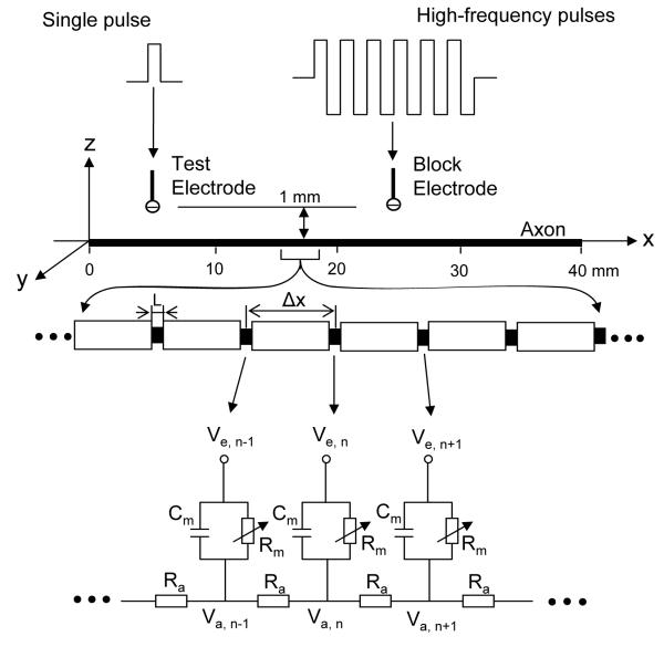
Fig. 1.
Axon model to simulate conduction block induced by high-frequency biphasic electrical currents. The inter-node length Δx = 100d; d is the axon diameter. L is the nodal length. Each node is modeled by a resistance-capacity circuit based on FH or CRRSS model. Ra: axoplasm resistance; Rm: membrane resistance; Cm: membrane capacitance; Va: intracellular potential; Ve: extracellular potential; Single pulse: 0.5-2 mA intensity, 0.1 ms pulse width; High-frequency pulses: 0-10 mA intensity, 1-20 kHz for FH model, 1-40 kHz for CRRSS model.

