Abstract
Coarse-grained molecular dynamics computer simulations are applied to investigate fundamental processes induced by an impact of keV C60 projectile at an organic overlayer composed of long, well-organized linear molecules. The energy transfer pathways, sputtering yields, and the damage induced in the irradiated system, represented by a Langmuir-Blodgett (LB) multilayers composed from molecules of bariated arachidic acid, are investigated as a function of the kinetic energy and impact angle of the projectile and the thickness of the organic system. In particular, the unique challenges of depth profiling through a LB film vs. a more isotropic solid are discussed.
The results indicate that the trajectories of projectile fragments and, consequently, the primary energy can be channeled by the geometrical structure of the overlayer. Although, a similar process is known from sputtering of single crystals by atomic projectiles, it has not been anticipated to occur during C60 bombardment due to the large size of the projectile. An open and ordered molecular structure of LB films is responsible for such behavior. Both the extent of damage and the efficiency of sputtering depend on the kinetic energy, the impact angle, and the layer thickness. The results indicate that the best depth profiling conditions can be achieved with low-energy cluster projectiles irradiating the organic overlayer at large off-normal angles.
Introduction
Energetic ion beams have become important processing and characterizing tools for a broad segment of the scientific and technological manufacturing sector. In particular, one of the most sensitive surface analysis techniques relies on uplifting of surface constituents by an impact of energetic projectiles followed by a mass analysis of the ionized (secondary ion mass spectrometry – SIMS) and neutral (secondary neutral mass spectrometry – SNMS) surface material.1 Both of these techniques are found to be particularly useful in chemical analysis of organic and biological structures.2 Cluster projectiles are especially interesting candidates for the surface probes in SIMS/SNMS as it has been found that the chemical surface analysis associated with lateral and vertical probing of material composition has become possible in many organic and biological systems.2-8 This success is mainly attributed to the enhanced sputter yields and lower damage accumulation of cluster bombardment, especially for the C60 projectile.9,10 All theoretical studies performed so far on organic systems have shown that the geometrical structure of irradiated solid does not have any influence on the energy deposition pathways of cluster projectiles, like C60.10-20 In all of these studies, the C60 projectile was quickly decelerated, depositing its kinetic energy close to the surface. The common feature of the substrates investigated computationally to date has been a relatively closed structure relative to the size and initial orientation of the incident C60 projectile.
Recently several experimental measurements have been published by Zheng and coworkers in which well-defined Langmuir-Blodgett (LB) multilayers of alternating barium arachidate and dimyristoyl phosphatidate (DMPA) deposited on bare silicon and Au-patterned silicon substrates are characterized by secondary ion mass spectrometry employing buckminsterfullerene (C60+) ion source.21-23 LB films were used in these studies to investigate the effect of various experimental parameters on the depth resolution of chemical analysis performed by a cluster ion beam. In particular, it has been observed that lowering of the impact kinetic energy and increasing the impact angle has a positive effect on the achievable depth resolution. The goal of this paper is to supply theoretical foundations for these observations. Of particular note is that the LB films are ordered films of long linear molecular chains with inter-chain spacing approximately the same size as the C60 projectile, perhaps allowing for different dynamics. Molecular dynamics (MD) computer simulations are used to investigate energy deposition pathways stimulated by an impact of C60 projectile in the LB films. In particular, the effect of the incidence energy, the impact angle, and the layer thickness on the efficiency of ejection and the ultimate resolution possible to achieve in the molecular depth profiling is studied.
Model
Details of MD computer simulations used to model C60 bombardment are described elsewhere.20 Briefly, the motion of the particles is determined by integrating Hamilton's equations of motion. In this study, we use a coarse-grained approach to model LB films formed from bariated molecules of arachidic acid (AA) deposited on an Ag{111}. In this approach, groups of atoms are represented as one united particle in order to reduce computational expense. The advantages of such approximation are that there are fewer particles, the potentials are simpler thus quicker to calculate, and the fast H-vibration is eliminated which allows for a larger time step to be used in the integration.19 As a result, the large systems required to realistically model keV fullerene interactions with organic solids can be treated within reasonable computational time. The downside of the united atom representation is the inability to consider broad-based chemical reactions. For instance, a proper description of such properties as bond order or bond saturation is missing. Furthermore, although the length and the strength of the bonds are described properly and molecules can be fragmented, only the fragments that originally belonged to the same pair of originally bound groups can recombine. Therefore, any conclusions about the chemistry of irradiated samples must be drawn with caution. Nevertheless, this technique has proven to significantly decrease simulation time while giving the results similar to the data obtained with a full atomistic model.13 In the coarse-grained approach each AA molecule is represented by a sequence of one COOBa (mass 182 Da), 18 CH2 (mass 14 Da each) and one CH3 (mass 15 Da) beads. With this arrangement, the total mass of a bariated AA molecule is 449 Da.
The forces among the particles are described by a blend of pair-wise additive and many-body potential energy functions. The Ag–Ag interactions are described by the MD/MC-CEM potential for metals.24 The interaction between C atoms in the projectile are described by the adaptive intermolecular potential, AIREBO.25 The interactions between projectile atoms and the rest of the system are described by a weak Lennard-Jones potential splined at small distances with a purely repulsive Moliere potential to better describe high energy collisions. A Lennard–Jones potential is also used to describe the interactions of the particles located in different molecules and the interaction between the components of a given molecule and the rest of the system. The parameters of these potentials, ε and σ, have been chosen from previous studies describing linear hydrocarbons and polymers,19,26-28 and to reproduce the molecular binding energy of cationized molecules of arachidic acid29 and the sublimation energy of arachidic acid, 2.1 eV.30 A Morse potential has been selected to describe interactions between adjacent particles (nearest neighbors) in the molecule. The parameters of this potential were selected to reflect the bond strength and equilibrium distance in linear hydrocarbons.19,26,27 The same potential with a small well depth is also used to model interactions between particles separated by one particle (next nearest neighbors). As a result the particles are allowed to interact if the molecule is dissociated, and the molecules adopt the appropriate zigzag shape in an equilibrium configuration.19 Finally, a Lennard-Jones potential is used to describe interactions between particles of a molecule that are separated by two or more beads to stabilize long range geometrical configuration of atoms in a molecule. These types of interactions have been preferred to an angle bend term adopted in studies of lipid films configurations which does not allow for dissociation and is, therefore, inappropriate for sputtering simulations.19 The parameters of potentials used to simulate interaction within the molecules and between the LB overlayer and the rest of the system overlayer are given in Table 1. There are no electrostatic interactions included in this study. It is known that such interactions occur in Langmuir-Blodgett systems.31 We believe, however, that the absence of these interactions will have only a minor effect on the processes initiated by high energy impacts as long as a proper value of the total binding energy is preserved. Finally, it should be also stressed that it is not the goal of this study to reproduce perfectly the structure of the organic film. Our goal is rather to investigate energy deposition and propagation in a model system that is composed from ordered long, linear molecules.
Table 1.
Parameters of Morse and 12-6 Lennard-Jones intramolecular interaction potentials. The 1-2 depicts the nearest neighbor interactions, 1-3 depicts the next nearest neighbor interactions and so on, rc is the potential cutoff distance.
| Morse | D (eV) | r0 (Å) | α (Å–1) | rc (Å) |
|---|---|---|---|---|
| CH2–CH2 | ||||
| 1–2 | 3.60 | 1.53 | 2.0 | 5.0 |
| 1–3 | 0.01 | 2.52 | 2.0 | 5.0 |
| CH2–CH3 | ||||
| 1–2 | 3.60 | 1.53 | 2.0 | 5.0 |
| 1–3 | 0.01 | 2.52 | 2.0 | 5.0 |
| CH2–COOBa | ||||
| 1–2 | 3.60 | 1.53 | 2.0 | 5.0 |
| 1–3 | 0.01 | 2.52 | 2.0 | 5.0 |
| Lennard–Jones “12–6” | ε (eV) | σ (Å) | rc (Å) | |
| CH2–CH2 | ||||
| 1–4 | 0.00520 | 3.80 | 7.65 | |
| 1–5 | 0.00390 | 5.09 | 7.65 | |
| CH2–CH3 | ||||
| 1–4 | 0.00620 | 3.80 | 7.65 | |
| 1–5 | 0.00465 | 5.09 | 7.65 | |
| CH2–COOBa | ||||
| 1–4 | 0.00620 | 3.80 | 7.65 | |
| 1–5 | 0.00465 | 5.09 | 7.65 | |
| Ag-CH2 | 0.015 | 3.47 | 6.0 | |
| Ag-CH3 | 0.015 | 3.47 | 6.0 | |
| Ag–COOBa | 0.21 | 2.30 | 5.0 | |
The model approximating LB films consisting of coarse-grained molecules deposited on Ag{111} is shown in Figure 1. The sample size was chosen to minimize edge effects associated with the dynamical events leading to ejection of particles. LB overlayers are represented by 1, 2, 3, 4 and 6 Y-type layers31 of coarse-grained bariated arachidic acid molecules deposited on the surface of the Ag crystal. The molecules were initially tilted by 22° along the surface normal.32 However, it has been found that during the equilibration procedure, when the kinetic energy of the system is drained out of the sample to allow it to assume the minimum potential energy configuration, the tilt angle is gradually reduced when moving from the metal/organic interface toward the organic surface. For instance, for a 4 layer system, the tilt angle varies from 22° for molecules adsorbed at the metal substrate to approximately 14° for molecules located at the topmost layer. The thickness of the organic overlayers is: 2.6 nm, 5.2 nm, 7.8 nm, 10.4 nm and 16.1 nm for 1, 2, 3, 4, and 6 layer systems, respectively. The monolayer thickness for AA is 2.7 nm as measured by ellipsometry.21 The substrate consisting of 607800 Ag atoms arranged in 30 layers is used in calculations with 1 and 2 layer LB systems. A thinner substrate consisting of 303900 atoms arranged in 15 layers is used for all other overlayers to speed up the calculation, as in these systems most of the primary kinetic energy is already absorbed in the organic overlayer. In the experiments performed by Zheng at al. LB films are not prepared on metal, but on semiconductor substrates.21-23 In the current study, however, a metal substrate was selected due to a simpler form of the potential, which results in much faster calculations. Silver was selected as a substrate because adsorption sites of AA on the Ag{111} surface could be arranged very close to the sites measured for AA/Si{100} system.33,34 The geometrical arrangement of the molecules, the adsorption sites, organic film density (mean area per molecule 0.19 nm2), and the value of the molecular-surface binding energy (sublimation energy of 2.1eV) were selected to reproduce the experimental data obtained for cationized arachidic acid adsorbed on Si{100}.28,33,34 Finally, special care was taken to eliminate artifacts associated with a possible backreflection of a pressure wave generated by an impact of cluster ions, as described in Ref. 9. Rigid and stochastic regions around the edge and the bottom of the samples are used as shown in Figure 1. It has been found that the tooth-saw shape of the stochastic zone is more effective in elimination of constructive interference of energy waves that reflect from the boundaries, than a simpler cylindrically-shaped zone.
Figure 1.
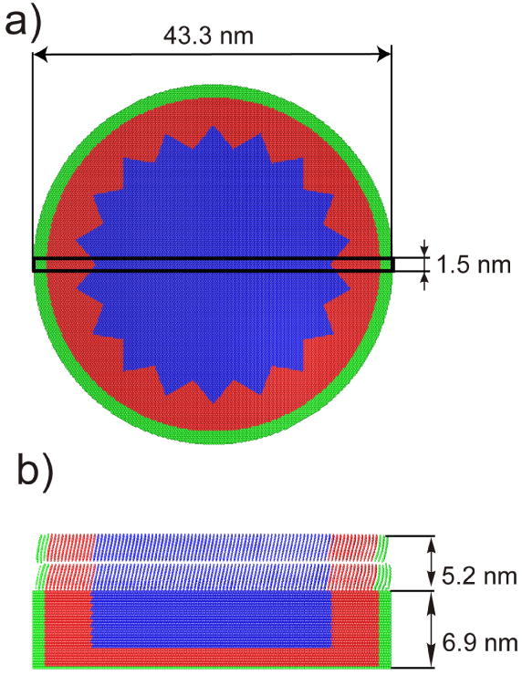
a) Top view and b) cross sectional view 1.5 nm wide on a two layer model system used in the simulations. The rectangle in panel a) depicts the location of the cross section shown in panel b). Particles forming stochastic and rigid zones are represented by red and green colors, respectively. Organic molecules are deposited in a Y type arrangement.
The atoms in the target initially have zero velocity. The atoms in the C60 projectile initially have no velocity relative to the center of mass motion. It is known that the motion induced by C60 bombardment is mostly independent of the initial aiming point.9,20 Consequently, only three trajectories were sampled for a given layer thickness, kinetic energy, and impact angle. Each trajectory was initiated with a fresh sample with all atoms in their equilibrium minimum energy positions. The impacts at low incidence angles are aimed at the centre of the surface. The impact points for large off-normal incidence angles (60° and 75°) were shifted in the direction opposite to projectile arrival by a 1/4 of the surface length to make sure that the collision cascades generated by such oblique impacts will be entirely contained within the sample. Each trajectory is terminated at 66 ps for 30 keV and 40 keV impacts, and at 46 ps in all other cases. It has been verified that these times are sufficient to properly describe the ejection process.
Results and Discussion
The main goal of the paper is to investigate theoretically the phenomena important for the cluster SIMS depth profiling of organic materials. Therefore, the paper is divided into three parts. The alteration of the original structure of the organic film induced by C60 impact is explored first. The emission efficiency and the composition of the ejected flux are investigated next. Finally, the role of the projectile parameters (the kinetic energy and the impact angle) on the depth resolution in molecular depth profiling is discussed.
Structure modifications
Snapshots of the temporal evolution of typical collision events leading to ejection of particles due to 15keV C60 impact on a 4 layer system at normal incidence are shown in Figure 2. The color scale reflects the amount of the particle displacement from the original position. An impact of a cluster projectile leads to a formation of a crater. There are many particles ejected, and the intact molecules compose a significant portion of the ejected flux. There are two observations that are particularly interesting. First, the shape of the crater created in the LB film by C60 impact is different from the shapes of craters formed in other organic systems investigated so far by computer modeling and the damage extends deep into the overlayer.10-12,14-19,31,35 While almost hemispherical craters surrounded by rims composed of relocated particles were observed in those studies, the crater formed in the LB overlayer is elongated and asymmetric. However, the relocated particles that are not ejected from the sample form a thin layer surrounding the crater walls. The snapshot representing the 1.5 nm cut through the sample centered at the cluster impact point collected at 1 ps suggests that the deposition of the primary energy can be channeled by the geometrical structure of the overlayer. This observation is unique among simulations of C60 bombardment of different materials. Although, a similar process is well known from sputtering of single crystals by atomic projectiles,36 it has not been anticipated to occur during C60 bombardment due to a large size of the projectile. To investigate this phenomenon more thoroughly a temporal evolution of the positions of projectile atoms forming 15keV C60 cluster bombarding 4 layer LB film at the early stages of sputtering is shown in Figure 3b. Indeed, it is evident that for both -25° and 0° impact angles, the trajectories of many carbon atoms are collimated and influenced by the initial orientation of organic molecules. Many of carbon atoms penetrate deep in the overlayer when the projectile impacts along directions close to the directions of molecular axes. In fact, a 4 layer LB film is not thick enough to stop many of these atoms. The calculations performed on a 6 layer system show that the penetration of 15 keV projectile atoms can extend up to 14 nm into the organic film, a depth 4-5 times larger than for keV C60 in materials like graphite,11,17 fullerite,17 molecular benzene,14,35 water ice,16 or polymer samples18,19. All previous theoretical studies with C60 projectiles have shown that the projectile atoms are almost immediately decelerated and the primary energy is deposited close to the surface.10-12,14-19,31,35 Such deposition scenario is, indeed, observed for 25°, and particularly for a 45° impact at AA film. Previous studies have also shown that the sample material is relocated by a concerted action of atoms composing the projectile. A formation of almost hemispherical craters was a consequence of such collective action. As it is visible in Figure 3b, the integrity of the projectile bombarding LB films in directions close to the surface normal is quickly compromised. This effect hampers the ability of these atoms to work in a collective manner. The lack of collective interactions as well as the collimating action of the organic film is responsible for a formation of an elongated crater.
Figure 2.
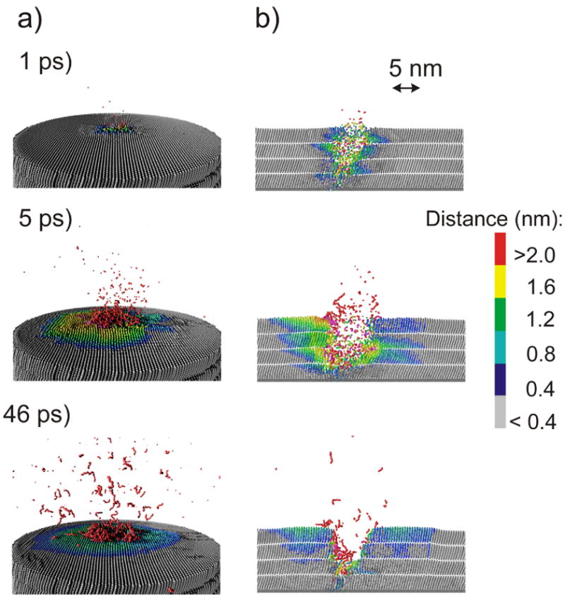
Cross sectional view of the temporal evolution of typical collision events leading to ejection of particles due to 15keV C60 impact at a 4 layer system at normal incidence. A slice 1.5 nm wide centered at the projectile impact is shown. The color scale reflects the amount of the particle displacement from the original position.
Figure 3.
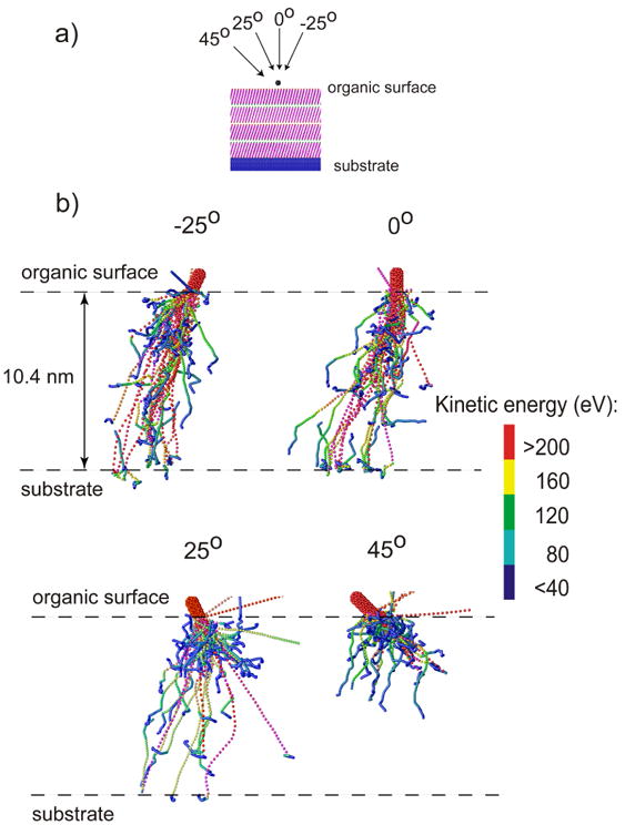
a) The definitions of the impact angles and b) the temporal evolution of the positions of projectile atoms forming 15 keV C60 cluster bombarding 4 layer AA film at -25°, 0°, 25°, 45°, at the early stages of sputtering (up to 400 fs). The color scheme represents the kinetic energy of individual atoms. The scale goes from red (most energetic atoms) to dark blue (the least energetic atoms).
The question arises, therefore, as to the reasons that are responsible for such different behavior of the C60 projectile in LB films as compared to all other organic samples investigated so far by computer modeling. The main difference is the geometrical structure of the overlayer. The LB overlayers are made from long, linear molecules that form an open and ordered network. In fact, each AA molecule occupies a cross-sectional area22,33 of almost 0.2 nm2. Thus, the distance between the molecules (∼0.47 nm) is comparable to the C60 diameter. The samples irradiated in the previous simulations studies were less open and more disorganized. As a result, atoms composing C60 cluster begin to interact simultaneously with many sample atoms immediately after the impact. The cluster projectile impacting the LB sample at directions close to the surface normal sees the organic layer as a low-density stockade with ends directed toward the cluster. As a result, the interaction between the projectile and the LB film is spatially localized around small areas, and consequently, C60 breaks into smaller pieces. The trajectories of these pieces can be subsequently collimated by the presence of open channels as long as the impact angle does not differ too much from the channel axis. The existence of the channels with relatively “smooth” walls leads to weak interactions between projectile atoms and the surrounding medium, as indicated in Figure 3b by the fact that some of the projectile atoms can retain their high kinetic energy even after penetrating 10 nm deep into the sample.
The shape of final craters and the dependence of the relative efficiency of molecular ejection on the original location of the molecules in the sample are shown in Figure 4 and Figure 5 for several primary kinetic energies of C60 projectile at normal incidence. Analogous graphs for 15 keV C60 arriving at the surface at several impact angles are shown in Figure 6 and Figure 7. For normal incidence, the size of the crater increases with the impact kinetic energy, however, the asymmetry of the crater shape is preserved. As shown in Figure 5 most of the ejected molecules originate from the topmost layer. However, the contribution of the molecules originally located deeper below the surface is not negligible especially for high kinetic energy. For instance, while 5 keV projectiles eject mostly particles located in the two topmost layers, 40 keV C60 cluster can emit molecules initially located in the 5th layer beneath the surface. As a consequence, the depth of the resulting crater changes from approximately 5 nm for 5 keV projectiles up to more than 14 nm for 40 keV C60 clusters.
Figure 4.
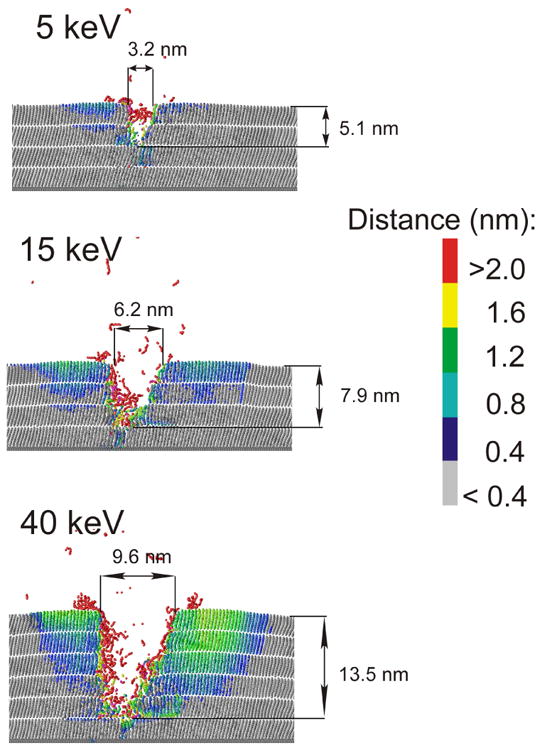
Cross sectional view of the craters created by C60 impact with several different kinetic energies at 46 ps (5 and 15 keV) and 66 ps (40 keV). The color scale reflects the amount of the particle displacement from the original position. A slice 1.5 nm wide centered at the projectile impact is shown.
Figure 5.
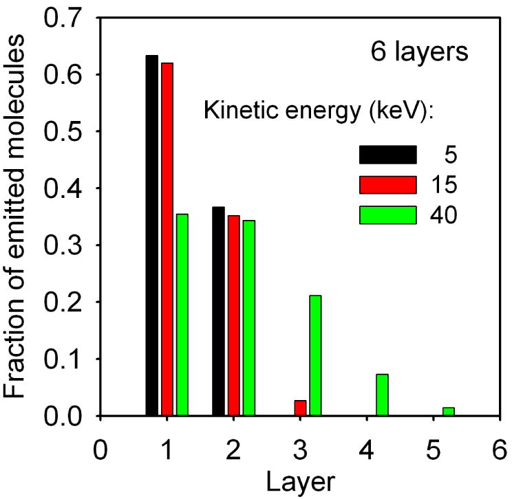
The fraction of all emitted molecules originating from a given layer of a 6 layer AA system bombarded at normal incidence with C60 projectiles with three different kinetic energies.
Figure 6.
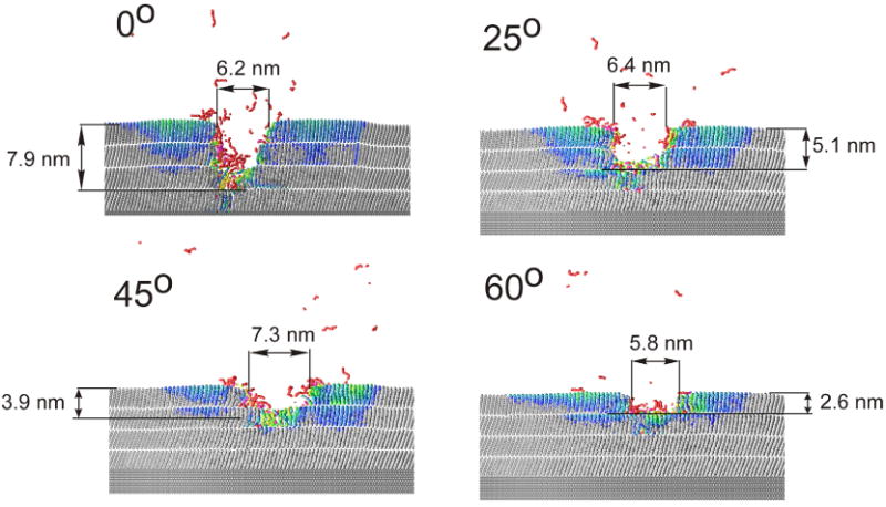
Cross sectional view of the craters created by 15 keV C60 impact on a 4 layer AA system at various impact angles at 46 ps. The color scale reflects the amount of the particle displacement from the original position. A slice 1.5 nm wide centered at the projectile impact is shown.
Figure 7.
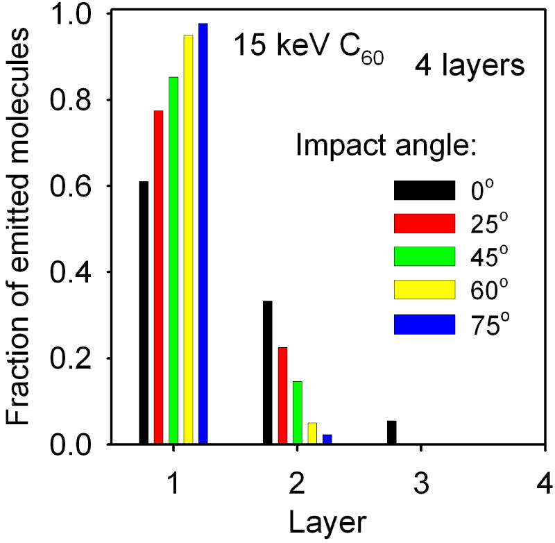
The dependence of the relative efficiency of particle ejection on the original depth of molecules emitted from a 4 layer AA system bombarded at various impact angles with 15 keV C60 projectiles. The graph shows the fraction of all ejected molecules that were originally located in a given layer.
As shown in Figure 6 and Figure 7, the extent of the sample damage is significantly reduced if the projectile is directed at larger impact angles. While a significant portion of particles eject from a depth of 5 nm by 15 keV C60 at normal incidence, most of the emitted material comes from the topmost layer for a 60° impact. The improvement is even more dramatic for 40 keV projectiles, where the ejection depth is reduced from ∼14 nm to ∼3 nm when the impact angle is changed for 0° to 60°. This phenomenon is known from studies on inorganic systems37 and model calculations.20,35 However, the degree of the improvement observed in LB systems could not be anticipated from previous studies of cluster induced sputtering.
Yields
As shown in Figure 2, the sputtered flux is composed from intact and fragmented molecules. The ejection is quite efficient. As presented in Table 3, 259 and 244 molecule equivalents (1.16×10⁵ and 1.10×10⁵ Da, respectively) are ejected on average for 20 keV fullerene at normal and 45° incidence from a 4 layer system, respectively. The experimental measurements made on an LB film of bariated arachidic acid at liquid nitrogen temperature show that approximately 230 and 225 molecules are ejected by a single 20 keV C60 at 5° and 45° impact, respectively.23,38 Both these numbers are in very good agreement with the calculated values taking into account approximations of the computer model. Moreover, these values are comparable with yields for other systems as compiled in Ref. 19 where the yield at 20 keV ranges from 4×10⁴ to 1.1×10⁵ Da for different systems. Both in simulations and in the experiment,21 intact molecules compose a significant portion of the emitted flux. The relative contribution of ejected intact molecules does not seem to depend on the layer thickness or the impact energy, and only slightly decreases with the increase of the impact angle. The last effect can be attributed to a larger chance of fragmenting the molecule when hit more perpendicularly to the molecular axis. The ejection of substrate atoms is negligible with exception of a monolayer and 2 layer systems and, except for these particular cases, these particles do not play any role in ejection of organic molecules.
Table 3.
The total sputtering yield Ytot and the partial sputtering yield Yp of intact molecules AA ejected from a 4 layer system by C60 projectiles with various primary kinetic energies Ekin and impact angles.
| Ekin (keV) |
Impact angle (deg) |
Ytot (molecules/ion) |
Yp (molecules/ion) |
|---|---|---|---|
| 5 | 0 | 28±2 | 13±2 |
| 10 | 0 | 81±7 | 47±6 |
| 15 | 0 | 161±6 | 89±6 |
| 15 | -25 | 155±4 | 84±3 |
| 15 | 25 | 187±3 | 94±3 |
| 15 | 45 | 163±1 | 83±3 |
| 15 | 60 | 106±4 | 38±2 |
| 15 | 75 | 39±5 | 10±3 |
| 20 | 0 | 259±16 | 150±8 |
| 20 | 45 | 244±7 | 124±8 |
| 30 | 0 | 433±23 | 268±7 |
| 40 | 0 | 558±29 | 366±13 |
| 40 | 45 | 570±26 | 316±16 |
The ejection efficiency depends on the overlayer thickness. As shown in Figure 8, at the beginning the total sputtering yield increases to a maximum with the increase of the thickness of the organic overlayer, then decreases and finally saturates. The same trend is also visible in the sputtering yield of intact molecules. A similar behavior of the sputtering yield on the organic overlayer thickness has been observed for Ar bombardment of adenine overlayers39 on Ag, or, recently, in experiments on cluster depth profiling of cholesterol film in which the erosion rate of organic material increases as the profiling beam gets near the silicon/organic interface.40 There are two factors that are responsible for such behavior. The first factor is the increase of the amount of the material available for sputtering from a thicker layer. However, this factor could account only for an initial increase and should finally lead to the signal saturation when the overlayer thickness exceeds the depth of the active volume contributing to sputtering.41 Therefore, just this factor alone can not explain the presence of the maximum in the spectrum. The second important factor is the influence of the organic/inorganic interface. The metal substrate used in this study is dense and is composed from atoms heavier that carbon. As a result, it can reflect the projectile atoms that arrive at the organic/metal interface back into the organic overlayer. A weak presence of such a process can be seen in Figure 3b for -25° and 0° impacts. The organic/substrate interface can also reflect a part of already deposited energy that propagates vertically within the organic film. Both these phenomena will increase the density of the energy in the near surface region, which, in turn, will enhance ejection. However, the role of the organic/substrate interface will decrease with the increase of the layer thickness because both a larger number of projectile atoms will be stopped in the organic film before reaching the organic/substrate interface, and less of the backreflected energy will be stored in the volume that actually can contribute to sputtering. This volume is located close to the surface.41 Thus, the further the organic/metal interface is from the surface the smaller amount of reflected energy can be stored in the active volume. The maximum visible in Figure 8 is, therefore, a result of interplay between these counteracting phenomena. This interpretation is additionally supported by the observation that the position of the maximum depends on the kinetic energy of the projectile. As visible in Figure 8, the position of the maximum shifts to thicker overlayers as the kinetic energy increases. This is a consequence of the increasing penetration depth of energetic projectile fragments, and a larger active volume being able to contribute to sputtering.41
Figure 8.
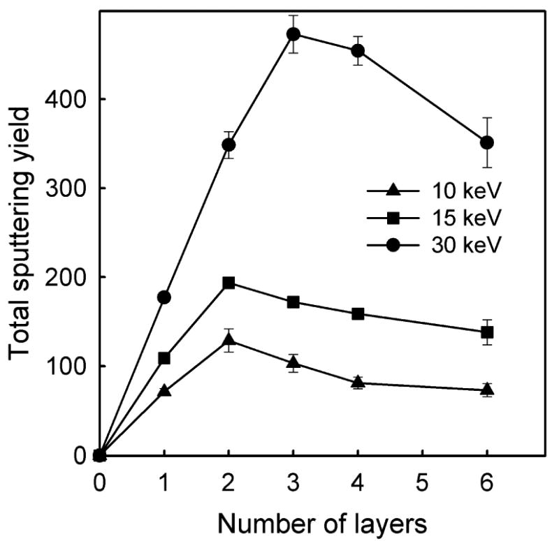
The dependence of the total sputtering yield of organic material on the AA film thickness for three different initial energies of the C60 projectile at normal incidence.
As already can be concluded from discussion given in a previous section, the sputtering yield is also sensitive to the kinetic energy of the C60 cluster. The dependence of the sputtering yield on the initial kinetic energy is shown in Figure 9 for C60 cluster impact at normal incidence on a 4 layer system. At the beginning the yield increases nonlinearly with the kinetic energy. However, at high kinetic energy the yield scales linearly with the impact energy. A linear region was observed in the experiment on LB films22 and is theoretically predicted for cluster bombardment41,42 and observed in other experiments as compiled in Ref. 19. Finally, the sputtering yield depends also on the projectile impact angle as shown in Figure 10 for 15 keV C60 cluster bombarding 2 and 4 layer system. It is interesting to note that the dependence is quite similar for both systems. A similar trend has also been observed in calculations for C60 bombardment of benzene35,40 and experiments of C60 bombardment of cholesterol.40 Some differences occur only at low impact angles. The yield of molecules ejected from 2 layer system is symmetric along the surface normal, while the yield from 4 layer system is slightly larger at 25° than -25°. The latter can be explained by the channeling action of the molecular structure. The projectiles impacting at -25° (the direction close to the tilt angle of the molecules) deposit their energy deeper than particles arriving at 25°, and, consequently stimulate lower ejection. It seems that proximity of the organic/metal interface in 2 layer system eliminates the effects of molecular arrangement, caused, most probably, by a significant contribution of backreflected projectile atoms into the total ejection, as these atoms will interact with already disrupted surface. The scale of a difference in the sputtering yields stimulated by -25° and 25° impacts will depend also on the projectile impact azimuth. It will be the largest for the azimuth selected in this study and smallest when the projectile arrives at the azimuth perpendicular to the one currently selected, i.e. perpendicular to the plane of molecular inclinations.
Figure 9.
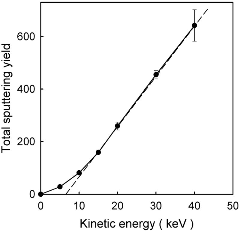
The dependence of the total sputtering yield on the kinetic energy of a C60 projectile bombarding a 4 layer AA system at normal incidence. A straight broken line was fit to the high energy part of the spectrum.
Figure 10.
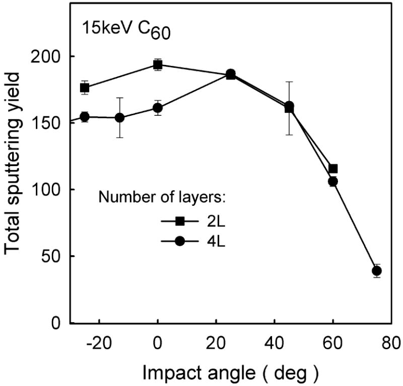
The dependence of the total sputtering yield of organic material on the impact angle of 15 keV C60 projectiles for 2 and 4 layer systems.
In principle, we would like to make a detailed and quantitative comparison to the experimental yields measured by Zheng et al.21-23 There are essential differences between the calculated and experimental conditions, however. The real LB film consists of multiple domains in which the molecules are tilted in different directions. Since the incident angle of the beam in the experiment is ∼45°, then the experimental data consists of an average of yields for the angles of incidence of +45°, -45° and every azimuth in between. The calculated yields are for only one orientation of the film. Although it might be tractable to average over many incident azimuthal angles, the other difference is that the calculations have been performed for a flat surface whereas the experimental measurements are for systems that have been depth profiled, and a rough topology has developed. The initial calculations for depth profiling of an atomic solid show quite clearly that the average yield decreases for roughened surfaces compared to flat surfaces.43 Performing simulations under depth profiling conditions is currently beyond the scope of possibility.
Apart from these differences, within a wide range of impact angles, the sputtering yield is weakly sensitive to this parameter on both systems. At first it may seem unexpected as it has been shown previously that the penetration depth decreases with the increase of the impact angle. However, as it can also be seen in Figure 6, a decrease of the penetration depth is accompanied by the increase of the lateral dimensions of the ejected volume. This latter process can compensate for a decrease of the penetration depth within a wide range of impact angles. Only when the impact angle exceeds 45 degrees does the signal begin to drop. This decrease is mostly caused by an increase of the fraction of the primary kinetic energy being carried away into the vacuum by backreflected projectile atoms. While approximately 1 keV of the primary kinetic energy is backreflected for 15 keV C60 projectile at 45° impact, almost 5 keV is carried away for 60° irradiation. The significant decrease of the sputtering yield observed in our calculations at angles above 45° is different from the data reported in experiment.22 The experimental measurements indicate that the sputtering yield is almost constant up to 75°.22 However, it has been suggested that the experimental sample exhibits a large fluctuation of the thickness.22 Such fluctuations will result in a large spread of actual impact angles, which could be a reason for this discrepancy.
Implications for depth profiling
There are several factors that can contribute to the final resolution or interface width in molecular depth profiling. These include the projectile penetration that causes damage/reactions, depth of origin of the sputtered species, ion-induced interface mixing, ion-induced chemical modifications, and lateral fluctuations of the film thickness. Most of these phenomena are beyond the scope of these calculations and are only now beginning to be modeled for atomic solids.43 There are some unique properties of the LB films as highlighted by these simulations that will influence the interface width in depth profiling. The big difference in C60 bombardment of the LB film as compared with bombardment of other, more isotropic solids, is the observation of a channeling type motion (Figures 2b, 3, 4) and, concomitantly, the relatively large depth of origin of sputtered molecules (Figure 5). The second difference is that the experimental film will have domains of molecules tilted towards various azimuthal angles, and the simulations demonstrate that the depth that the C60 penetrates (Figure 6) and the depth of origin of sputtered molecules (Figure 7) depend strongly on the orientation of the beam relative to the tilt direction of the molecules. We believe that both of these factors will make interface widths larger for LB films than more isotropic solids. In concurrence with this suggestion, the depth profiling experiments utilizing C60 in which interface widths between similar materials such as two metals44,45 or two Langmuir-Blodgett films21,22 give values 8.7 and ∼23 nm respectively.
Conclusions
Coarse-grained molecular dynamics computer simulations have been employed to investigate the sputtering process of a multilayer of bariated arachidic acid system composed of long, well-organized linear molecules induced by an impact of energetic C60 projectiles. The simulations indicate that the trajectories of projectile fragments and, consequently, the primary kinetic energy can be channeled by the geometrical structure of the overlayer. Although, a similar process is well known from sputtering of single crystals by atomic projectiles, it has not been anticipated to occur during C60 bombardment due to the large size of the projectile. An open molecular structure of LB films is responsible for such behavior. Both the kinetic energy of the projectile and the impact angle have a pronounced influence on the efficiency of the molecular ejection and the extent of the damage induced in the irradiated samples. Above a certain threshold, kinetic energy the sputtering yield increases linearly with the primary kinetic energy. The yield was found to decrease with the impact angle, although, the change is relatively small up to approximately 45°. For a constant primary kinetic energy, the ejection efficiency depends on the layer thickness. The sputtering yield first increases with the increase of the thickness, reaches the maximum, decreases and finally saturates. The position of the maximum shifts to thicker overlayers with the increase of the projectile kinetic energy. The presence of the maximum is a result of a competition between signal enhancement due to increasing number of organic molecules and signal decrease due to lowering of the amount of the primary energy being backreflected into the organic overlayer by the receding organic/metal interface. When the sample thickness becomes much larger than the penetration depth of the projectile, the sputtering yield is independent of thickness. The simulations indicate that the projectiles can penetrate deep into the Langmuir-Blodgett film. This unusually long penetration is a result of a channeling of projectile atoms by an ordered and open molecular structure. Large projectile penetration leads to a significant depth of ion-induced damage. Both the size of damaged volume and the depth of ejected material increase with the projectile kinetic energy. Both these quantities also decrease with the impact angle. These observations indicate that the depth profiling should be made at high impact angles with the lowest kinetic energy. The results of our calculations compare well with the experimental findings.
Table 2.
Parameters of 12-6 Lennard-Jones potentials used to describe intermolecular interactions and the interactions of atoms composing a given molecule and the rest of the system. rc is the potential cutoff distance.
| Lennard–Jones “12–6” | ε (eV) | σ (Å) | rc (Å) |
|---|---|---|---|
| CH2–CH2 | 0.048 | 4.95 | 7.65 |
| CH2–CH3 | 0.005 | 4.95 | 7.65 |
| CH3–CH3 | 0.14 | 4.95 | 7.65 |
| CH3–COOBa | 0.005 | 4.95 | 7.65 |
| CH2–COOBa | 0.005 | 4.95 | 7.65 |
| COOBa –COOBa | 0.14 | 4.95 | 7.65 |
| Ag-CH2 | 0.015 | 3.47 | 6.00 |
| Ag-CH3 | 0.015 | 3.47 | 6.00 |
| Ag–COOBa | 0.21 | 2.3 | 5.00 |
| C-CH2, C-CH3, C-COOBa | 0.004 | 3.7 | 7.65 |
| C-Ag | 0.004 | 3.7 | 7.65 |
Acknowledgments
The financial support from the Polish Ministry of Science and Higher Education programs no. PB 4097/H03/2007/33 and PB 0935/B/H03/2008/35. BJG acknowledges support from the National Science Foundation grant CHE-0456514 and NW acknowledges support from the National Institute of Health under grants EB002016-13 and GM069338, the National Science Foundation grant CHE-0555314, and the Department of Energy grant DE-FG02-06ER15803.
References
- 1.Griffiths J. Analytical Chemistry. 2008;80:7194. doi: 10.1021/ac801528u. and references therein. [DOI] [PubMed] [Google Scholar]
- 2.Winograd N. Analytical Chemistry. 2005;77:142A. doi: 10.1021/ac051263k. and references therein. [DOI] [PubMed] [Google Scholar]
- 3.Cheng J, Winograd N. Analytical Chemistry. 2005;77:3651. doi: 10.1021/ac048131w. [DOI] [PubMed] [Google Scholar]
- 4.Fletcher JS, Conlan XA, Jones EA, Biddulph G, Lockyer NP, Vickerman JC. Analytical Chemistry. 2006;78:1827. doi: 10.1021/ac051624w. [DOI] [PubMed] [Google Scholar]
- 5.Fletcher JS, Lockyer NP, Vaidyanathan S, Vickerman JC. Analytical Chemistry. 2007;79:2199. doi: 10.1021/ac061370u. [DOI] [PubMed] [Google Scholar]
- 6.Shard AG, Brewer PJ, Green FM, Gilmore IS. Surface and Interface Analysis. 2007;39:294. [Google Scholar]
- 7.Shard AG, Green FM, Brewer PJ, Seah MP, Gilmore IS. Journal of Physical Chemistry B. 2008;112:2596. doi: 10.1021/jp077325n. [DOI] [PubMed] [Google Scholar]
- 8.Jones EA, Lockyer NP, Vickerman JC. Analytical Chemistry. 2008;80:2125. doi: 10.1021/ac702127q. [DOI] [PubMed] [Google Scholar]
- 9.Postawa Z, Czerwinski B, Szewczyk M, Smiley EJ, Winograd N, Garrison BJ. Analytical Chemistry. 2003;75:4402. doi: 10.1021/ac034387a. [DOI] [PubMed] [Google Scholar]
- 10.Postawa Z, Czerwinski B, Szewczyk M, Smiley EJ, Winograd N, Garrison BJ. Journal of Physical Chemistry B. 2004;108:7831. [Google Scholar]
- 11.Webb R, Kerford M, Kappes M, Brauchle G. Radiation Effects and Defects in Solids. 1997;142:23. [Google Scholar]
- 12.Krantzman KD, Postawa Z, Garrison BJ, Winograd N, Stuart SJ, Harrison JA. Nuclear Instruments & Methods in Physics Research Section B-Beam Interactions with Materials and Atoms. 2001;180:159. [Google Scholar]
- 13.Smiley EJ, Postawa Z, Wojciechowski IA, Winograd N, Garrison BJ. Applied Surface Science. 2006;252:6436. [Google Scholar]
- 14.Smiley EJ, Winograd N, Garrison BJ. Analytical Chemistry. 2007;79:494. doi: 10.1021/ac061531u. [DOI] [PubMed] [Google Scholar]
- 15.Ryan KE, Smiley EJ, Winograd N, Garrison BJ. Applied Surface Science. 2008;255:844. [Google Scholar]
- 16.Russo MF, Jr, Szakal C, Kozole J, Winograd N, Garrison BJ. Analytical Chemistry. 2007;79:4493. doi: 10.1021/ac070105l. [DOI] [PMC free article] [PubMed] [Google Scholar]
- 17.Anders C, Kirihata H, Yamaguchi Y, Urbassek HM. Nuclear Instruments and Methods in Physics Research Section B: Beam Interactions with Materials and Atoms. 2007;255:247. [Google Scholar]
- 18.Delcorte A, Garrison BJ. Nuclear Instruments and Methods in Physics Research Section B: Beam Interactions with Materials and Atoms. 2007;255:223. doi: 10.1016/j.nimb.2007.02.004. [DOI] [PMC free article] [PubMed] [Google Scholar]
- 19.Delcorte A, Garrison BJ. Journal of Physical Chemistry. 2007;111:15312. [Google Scholar]
- 20.Garrison BJ, Postawa Z. Mass Spectrometry Reviews. 2008;27:289. doi: 10.1002/mas.20165. and references therein. [DOI] [PubMed] [Google Scholar]
- 21.Zheng L, Wucher A, Winograd N. Journal of American Society of Mass Spectrometry. 2008;19:96. doi: 10.1016/j.jasms.2007.10.020. [DOI] [PMC free article] [PubMed] [Google Scholar]
- 22.Zheng L, Wucher A, Winograd N. Analytical Chemistry. 2008;80:7363. doi: 10.1021/ac801056f. [DOI] [PMC free article] [PubMed] [Google Scholar]
- 23.Zheng L. PhD Thesis. The Pennsylvania State University; 2008. Langmuir-Blodgett films as models for TOF-SIMS investigation of biological systems. [Google Scholar]
- 24.Kelchner CL, Halstead DM, Perkins LS, Wallace NM, Depristo AE. Surface Science. 1994;310:425. [Google Scholar]
- 25.Stuart SJ, Tutein AB, Harrison JA. Journal of Chemical Physics. 2000;112:6472. [Google Scholar]
- 26.Hautman J, Klein ML. Journal of Chemical Physics. 1989;91:4994. [Google Scholar]
- 27.Balasubramanian S, Klein ML, Siepmann JI. Journal of Chemical Physics. 1995;103:3184. [Google Scholar]
- 28.Saint-Pierre M, Dupeyrat M. Thin Solid Films. 1983;99:205. [Google Scholar]
- 29.Tippmann-Krayer P, Mohwald H. Journal of Physical Chemistry. 1992;96:5220. [Google Scholar]
- 30.Merkel KS. Fatty Acids: Their Chemistry, Properties, Production and Uses. Interface Publishers; New York: 1967. [Google Scholar]
- 31.Roberts G. Langmuir-Blodget Films. Plenum Press; New York and London: 1990. [Google Scholar]
- 32.Oncins G, Torrent-Burgues J, Sanz F. Journal of Physical Chemistry C. 2008;112:1967. [Google Scholar]
- 33.Takamoto D, Aydil E, Zasadzinski J, Ivanova A, Schwartz D, Yang T. Science. 1991;293:1292. doi: 10.1126/science.1060018. [DOI] [PubMed] [Google Scholar]
- 34.Seidel M, Chen S, Zewail A. Journal of Physical Chemistry. 2007;111:4920. [Google Scholar]
- 35.Ryan KE, Garrison BJ. Analytical Chemistry. 2008;80:5302. doi: 10.1021/ac800287k. [DOI] [PubMed] [Google Scholar]
- 36.Roosendaal HE, editor. Sputtering by Particle Bombardment I. Vol. 47. Springer; Berlin, Heidelberg: 1981. and references therein. [Google Scholar]
- 37.Hofmann S. Philos Tr R Soc S-A. 2004;362:55. doi: 10.1098/rsta.2003.1304. [DOI] [PubMed] [Google Scholar]
- 38.Zheng L. private communication [Google Scholar]
- 39.Schnieders A, Möllers R, Benninghoven A. Surface Science. 2001;471:170. [Google Scholar]
- 40.Kozole J, Wucher A, Winograd N. Analytical Chemistry. 2008;80:5293. doi: 10.1021/ac8002962. [DOI] [PMC free article] [PubMed] [Google Scholar]
- 41.Russo MF, Jr, Garrison BJ. Analytical Chemistry. 2006;78:7206. doi: 10.1021/ac061180j. [DOI] [PubMed] [Google Scholar]
- 42.Anders C, Urbassek HM. Physical Review B. 2004;70:155404. [Google Scholar]
- 43.Russo MF, Postawa Z, Garrison BJ. Journal of Physical Chemistry C. in press. [Google Scholar]
- 44.Sun S, Szakal C, Roll T, Mazarov P, Wucher A, Winograd N. Surface and Interface Analysis. 2004;36:1367. [Google Scholar]
- 45.Sun S, Wucher A, Szakal C, Winograd N. Applied Physics Letters. 2004;84:5177. [Google Scholar]


