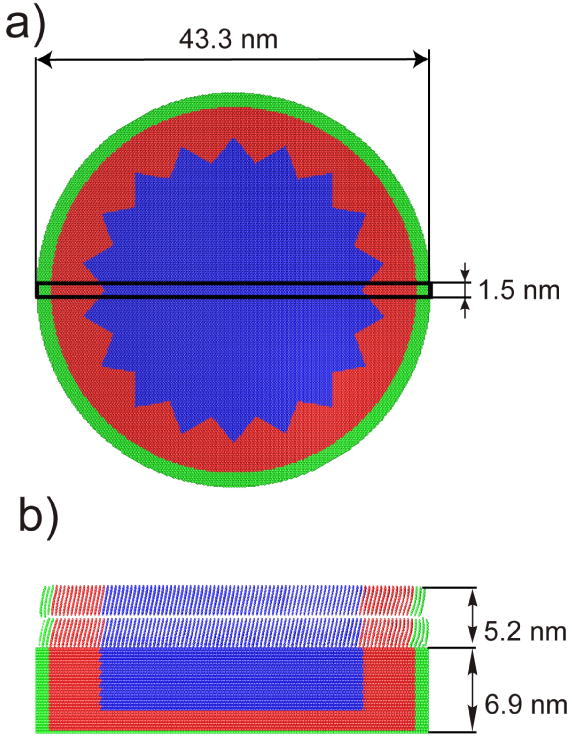
Figure 1.

a) Top view and b) cross sectional view 1.5 nm wide on a two layer model system used in the simulations. The rectangle in panel a) depicts the location of the cross section shown in panel b). Particles forming stochastic and rigid zones are represented by red and green colors, respectively. Organic molecules are deposited in a Y type arrangement.
