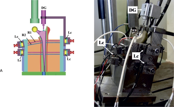
Figure 3.
A. An illustration of the tester. The measuring rod (R1 and R2) penetrating the fixator and the femur was placed at the cement-bone interface. Compressive force was measured with the load cell (Lc) via the upper rod (R1) in each site. The amount of cement creep was measured via the lower rod (R2). Stem subsidence was measured with the digital dial gauge (DG) contacting the upper end of the stem. B. The actual tester. The inside was inclined 15 degrees from the base on the coronary plane so that the load was applied to the femur head attached to the top of the stem from 15 degrees inside.

