
Fig. 6.
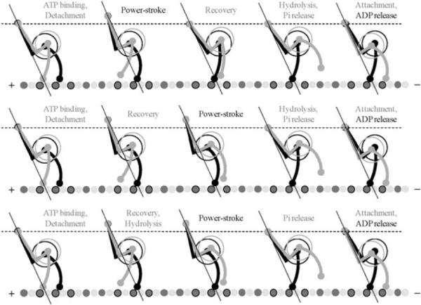
Detailed model for the two-headed dynein stepping consistent with both the two-headed kinetic model shown in Fig. 5 and experimentally observed conformational changes associated with pre-stroke and post-stroke states (Burgess et al.)1 Each of three stepping sequences corresponds to one of the parallel pathways in the kinetic model. The straight lines coming through the tail junction and one of the MTBD indicate the force line, along which the power-stroke opposes the external load. The load switches its carrier upon the detachment of the tailing head. The intermediate motion of the tail junction has both horizontal and vertical components, but each full cycle results in only horizontal displacement toward the minus end of the MT.