
Fig. 8.
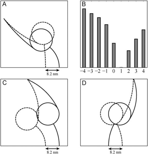
(A) The minimal bending energy geometry of dynein motor units in post-stroke (dashed lines) and pre-stroke (solid lines) states with their MTBD separated by 8.2 nm. At the points of attachment the stalk are enforced to be perpendicular to the MT; (B) Relative minimum bending energy (in arbitrary units) of the two-headed dynein as a function of the MTBD separation on the MT (in units of 8.2 nm). Plus and minus signs correspond to the attachment of the pre-stroke head in front and behind the other head, respectively. Here and throughout the paper `front' means toward the minus end of the MT; (C, D) The same as (A) but for the (−7) construct, in which the ring-tail complex of each head is flipped with respect to the stalk. All other geometrical parameters and conditions were left unaltered. The difference between (C) and (D) is in the relative position of the head's MTBDs on the microtubule, leading to the motion in the opposite directions according to the detailed two-headed model shown in Fig. 6.