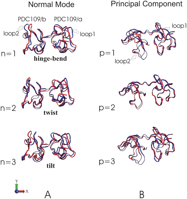
Figure 12. Comparison of the first three normal modes and principal components.
Overlapping ribbon conformations for the three lowest normal modes are shown at t = 0 (red) and  (blue) with the normalized eigenvector vibrational amplitudes scaled by a factor of 200. The normal mode index
  corresponds to specific vibrational frequencies as follows:
  = 1 (hinge-bend),
  0.80 cm
 ;
;  = 2 (twist),
  1.72 cm
 ;
;  = 3 (tilt),
  3.08 cm
 . Overlapping ribbon conformations for the three largest amplitude principal components (p = 1, 2, 3) are shown with the reference structure (red) as displacements scaled by a factor of 200 standard deviations along each principal component (blue) [74].

